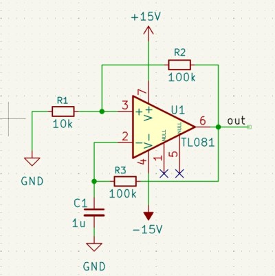
Some people learning the noble art of electronics find the jump from simpler tools like Fritzing to more complex ones, such as KiCAD, a little daunting, especially since they need to learn at least two tools. Fritzing is great for visualising your breadboard layout, but what if you want to start from a proper schematic, make a prototype on a breadboard and then design a custom PCB? Well, with the Kicad-breadboard plugin for (you guessed it!) KiCAD, you can now do all of this in the same tool.
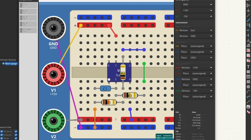
Originally designed to support EE students at the University of Antwerp, the tool presents you with a virtual breadboard with configurable size and style, along with a list of components and tools that can be placed. A few clicks and parts can be placed on the virtual breadboard with ease. Adding wires is the next logical step to make those connections that operate in the horizontal dimension. Finally, assigning power supplies and probe connections completes the process. It’s a simple enough tool to draw stuff, but drawing a layout is no use if you can’t verify it’s correctness. This is where this plugin shines: it can perform an ERC (check) between the schematic and the breadboard and flag up what you missed. Add to this that you can also perform an ERC at the schematic level, before even thinking about layout, and it’s pretty hard to make an error. Now, you can transfer this directly to a real breadboard, or even a veroboard, for more permanence once you have confidence in correctness. This will definitely save time correcting errors and help keep the magic smoke safely contained within those mysterious black rectangles.
As it stands, the tools are limited to a few select ICs, which, much to this scribe’s disappointment, did not include the venerable 555 timer; however, it would be possible to work around that with some imagination at the schematic level. The ability to drop in and document power supply, function generator, and oscilloscope probing points is nice, enabling one to close the loop on documenting a layout to make it truly transferable to physical reality.
We cover electronics prototyping with breadboards a lot because they’re accessible. Here’s a super simple computer on a breadboard. We also like seeing them integrated as tools, like here. Finally, why stick with the tired old common breadboard shapes when you could make your own?


This might interest you
https://techxplore.com/
The future
https://techxplore.com/news/2026-04-3d-device-harnesses-brain-cells.html
Now .. moisturize me…
This is pretty amazing actually. I do a lot of bread boarding because I suck at electronics and this would be useful to me. Especially if they added lots of ICs like op amps.
My kids are going to benefit from this, thanks Robin Kerstens!
Hooray! Now people who hate Fritzing can still participate.
Fritzing is on an UI/UX level of sophistication that typically needs government funding to manifest.
There’s a nice, pretty comprehensive, bit of software that used to go by the name, Crocodile Clips. The latest versions are paid/subscription, but older versions are more accessible. There’s full schematic design, digital and analogue or a mixture of the two and child friendly pictorial block design mode, you can add multiple virtual oscilloscopes, program virtual microcontrollers, even create your own custom chips and components. Personally I find the interface on the older versions more intuitive than something like Spice. There’s even built in tutorials for use as a teaching aid.
It was good for basic testing but it was also pretty easy to break, especially using the mechanical side of it. You could connect a motor and generator together, apply power to make the motor spin then remove the power again and if the generator and motor are connected electrically it will form a feedback loop that instead of decaying to 0 keeps increasing infinitely until the program crashes. So that makes me doubt how accurate it’s simulation is.
Also… Ford those shopping around. ‘Circuit wizard’ by new wave concepts. It has schematic view, breadboard, even simulated pcbs and hundreds of 4000 and 7400 series ICs modelled as well as op amps and 555, and a great UI which is far slicker IMO. It’s how I deliver circuit design teaching in the UK and have done for a while. That, and Arduino and breaboarding is simulated in tinkercad very well
Why would one be shopping? That’s one of the big downfall of fritzing they want stuff in return for “connect pico to Qwiic connector to do dad’s Qwiic connector”
It was eye rolling in 2006 now its just a blatant grift
Cool!
Do we have a VS (Virtual Soldering) plugin yet ? ;)
Does anyone have a way to plan the scoring of copper clad boards to make islands to connect your components?
I can mentally do it if there are 3-4 components but any more and i need to constantly double check the pinout
It is quite easy to use KiCad to plan the footprint placement and at least partial layout on strip board.
You can even enable some extra copper layers to simulate “air wiring”.
There is also the (commercial) software “Lochmaster” from Abacom. I once thought of buying some Abacom software (Before I discovered KiCad) but that software has no connection between a “schematic” and “PCB”. So no ERC or DRC. And therefore I quickly lost interest in that software.
There are many proprietary products and homebrew mechanisms.
Have a look at https://entertaininghacks.wordpress.com/2020/07/22/prototyping-circuits-easy-cheap-fast-reliable-techniques/ and choose the combination that suits your current circuit.
Also, for one surprising consequence of using solderless breadboards, see https://entertaininghacks.wordpress.com/2024/03/16/practical-traps-with-a-one-transistor-audio-amplifier-solderless-breadboards-and-oscilloscopes/ Try to work out what’s happening before you reach the end :)
Thank you, that last link was particularly interesting!
Glad it was interesting, and hopefully helps you recognise pitfalls when you have fallen into one.
And we all fall into traps occasionally!
I think you could probably use the PCB tool for that. Lay everything out, draw lines between components where you would cut and then print it out on a piece of paper and cut over it.
Maybe it would be better if you connected as much as you could with traces and then just draw a box around the trace that you could score with a ruler and knife?
I had the following thoughts.
1. what is keeping this from being an official repo?
2. With the vast 3D bodies available and the internal simulator available why is the parts list so limited?
conceptually its a great idea for spinning up a prototype and then transitioning to a fabrication.