
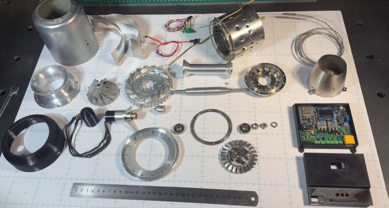
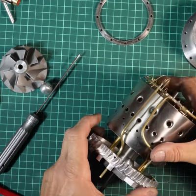
 After many months of painstaking work, [AlfMart CNC Garage] over at YouTube has finally reached the stage where he can fully assemble his DIY jet turbine and commence testing. Even if deceptively simple devices, just the starting mechanism turned out to be a challenge. Due to the extreme conditions that these jet turbines operate under, tolerances are narrow, and many of the materials require careful selecting and testing.
Fortunately this is not true for the outer casing, which is cobbled together from a commercial gas cylinder and a children’s steel drinking bottle that so happened to have the right dimensions. From there the parts get increasingly more specialized, down to the carefully balanced rotor. Assuming everything was done right up till this point, the first start-up will mean a happily roaring turbine and not a deafening explosion followed by a cloud of shrapnel.
In the video the full assembly can be observed, along with detailed instructions should anyone want to follow along with their own DIY jet turbine. Naturally a lot of attention has to be paid to tolerances during the assembly process. Following the basic turbine assembly, the RPM sensor circuit and the electrical starter are added, with the latter allowing for the turbine to spin up prior to ignition.
The first basic starter tests revealed an issue with the starter motor and clutch mechanism, requiring some upgrades. Before the first ignition the whole turbine has to be dynamically balanced, for which first a new balancing rig will be designed and assembled. While this means that first ignition will still be a while off, it’s best to take projects like this slow and steady. We’re also looking forward to seeing this new dynamic balancing rig that’s claimed to be much more advanced than that used for balancing the rotor.












Its a singular achievement. But you do know you can buy these things mail order, don’t you? They’re difficult to make, people have been pecking at the problem for decades, but in recent years they and their associated engine management systems have been sorted to the point that a dedicated model aircraft builder can build a realistic looking, sounding and flying jet.
yeah you can “mail order” them…
JetCat P100-RX: Approx. $2,500 – $2,600 (22.5 lbs thrust)
JetCat P350-Pro-S: Approx. $7,399 – $7,795 (78.7 lbs thrust)
But thats only $400-800 in materials once you get all the particulars sorted and can make duplicates of your own design. If youre trying to build your own Airboard, or jetpack, or any of the other multijet flying machines being able to build them yourself, and service them with parts you make yourself, is a major long term asset.
and this is HAD not You Can Amazon A Day.
I feel like that isn’t exactly in the spirit of Hackaday.
There’s a significant difference between ‘ I bought a mini jet engine ‘ and ‘i just built a small gas turbine engine from scratch’
I’ve always lusted after these mini jets. Also always been curious how they’re lubricated while running. Those bearings must be screaming after a flight.
Same concept as glow engines, you mix fuel and lubricant together. You need a pretty hearty synthetic that isn’t going to burn under the extreme conditions. It’s going to be more finicky than glow engines though, which typically use a castor oil base that have a lot of benefits for simple piston engines.
The little ones use small percentage of specialized turbine oil (such as Mobil JET Oil II) is mixed directly into the fuel (Kerosene or Jet A), which lubricates the ceramic bearings as it passes through the engine.
The bigger ones like the JetCat-PRO series use a secondary oil feeder pump and reservoir to lubricate the bearings without needing to mix oil into the main fuel tank
A few helpful hints for the guy who made the video…
1. kV where motors are concerned is NOT KiloVolts, it is instead the name given to the voltage constant, commonly specified in units of “rpm per volt of supply”, 8.3/kV gives a torque constant in “Nm per Amp”.
2. You can spin brushless motors up to speed under any load if you manually add some magnets on the shaft to be detected by hall sensors, or otherwise add an encoder or other means to measure rotation angle, then you can drive with a sensored rather than sensorless control logic where the phases being powered always match what is necessary to be 90 electrical degrees (90 real physical degrees divided by pole pair count) ahead of where the rotor is right now. Look up “Field oriented control” and then look at the most basic ways of doing it with hall sensors, or even just using hall sensors as the guide for 6 step commutation.
Very nice project, hope this helps make things easier for you in the next thing you build.
I would love to know where the design came from. Obviously it’s similar to existing micro-turbine engines, but did he copy it from a commercial model? Or are there existing open source plans? I would love to download cad files of the design.
CAD files are available for premium customer only sorry. If you want buy them contact me @facebook
Looking forward to hearing from you Sir!
This could be a false memory (it’s been a while) but…
When I first saw AutoCad, running on an 8086 CPU, it was slowly drawing a bunch of stuff.
One was a spacecraft (Voyager?) and I think another was an engine. Car? Jet? Too far back to recall details.
Point is – there are a lot of CAD drawings out there.
You could take a look at where home jet engine building started – Kurt Schreckling’s classic book ‘Gas Turbine Engines for Model Aircraft’ published back in 1992. It details the formulae for components and has complete plans:
https://ia601901.us.archive.org/22/items/modelenginelibrary/GasTurbineEngines_forModelAircraft_Schreckling_text.pdf
Note that his compressor is made from plywood, bound with carbon fibre around the circumference. I bought this book thirty years ago and has been gathering dust nicely on my bookshelf ever since.
Comment on another video in the series:
“The design is higly based on the KJ66 and GR 130 models, with some modifications to adapt it to my tooling”
Found it:
http://www.gerald-rutten.nl/turbines.htm
Long time since I learned about jet engine design, but one of the major aspects is the compressor design. I see here we’re using a centrifugal compressor. This steems counterintuitive because the air has to turn through 90 degrees twice on the way through the engine. Why the choice of a centrifugal compressor design – is it fluid dynamics based (impossible to create the compression with a scaled radial compressor?) or ease of finding parts?
My understanding is that centrifugal compressors are easier, to build and to function.
Remember initial jet engines were mostly centrifugal i.e. Rolls Royce Derwent, Nene. Also used for small/reduced size engines i.e. APU (auxiliary power units)
Not a fan of the AI narration. 3300 Killo volts motor? 3300kv motor has a whole other meaning.
This is probably one of the best uses for AI. The creator is not an English speaker and without the help of AI tools we’d likely not get this project in English. I’d rather the often weird AI than no project at all or a project in a language I don’t understand.