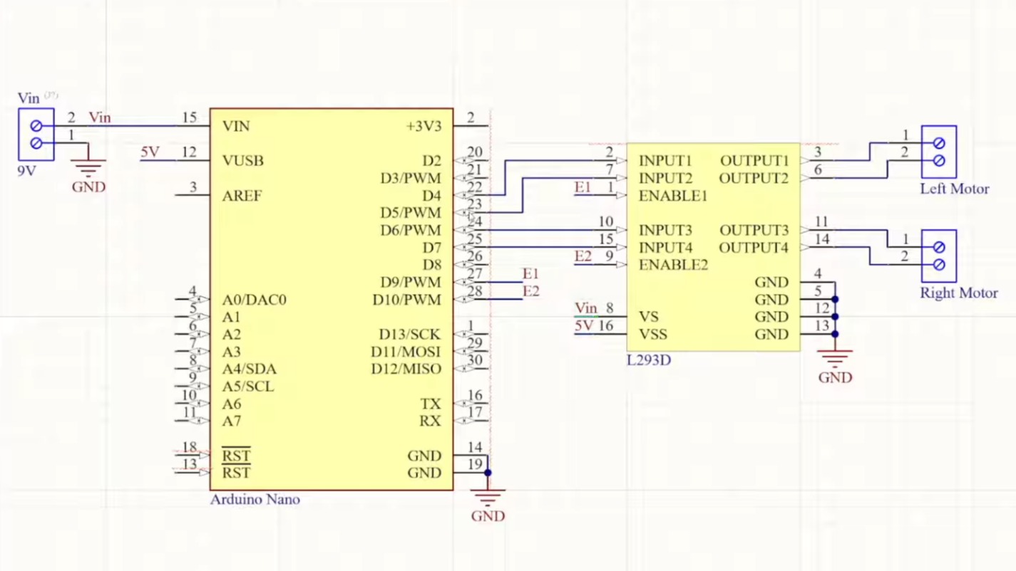
A view of the schematics for each major component.

Simulating The Commodore PET

Over on his blog our hacker [cpt_tom] shows us how to simulate the hardware for a Commodore PET. Two of them in fact, one with static RAM and the other with dynamic RAM.

This project is serious business. The simulation environment used is Digital. Digital is a digital logic designer and circuit simulator designed for educational purposes. It’s a Java program that runs under the JVM. It deals in .dig files which are XML files that represent the details of the simulated hardware components. You don’t need to write the XML files by hand, there is a GUI for that. Continue reading “Simulating The Commodore PET”

A photo montage of scrap plastic being vacuumed up, processed in the main chamber, and bottled in gas tanks.

Solar Powered Pyrolysis Facility Converts Scrap Plastic Into Fuel

[naturejab] shows off his solar powered pyrolysis machine which can convert scrap plastic into fuel. According to the video, this is the world’s most complex hand-made pyrolysis reactor ever made. We will give him some wiggle room there around “complex” and “hand-made”, because whatever else you have to say about it this machine is incredibly cool!

As you may know pyrolysis is a process wherein heat is applied to organic material in an inert environment (such as a vacuum) which causes the separation of its covalent bonds thereby causing it to decompose. In this case we decompose scrap plastic into what it was made from: natural gas and petroleum.

His facility is one hundred percent solar powered. The battery is a 100 kWh Komodo commercial power tank. He has in the order of twenty solar power panels laying in the grass behind the facility giving him eight or nine kilowatts. The first step in using the machine, after turning it on, is to load scrap plastic into it; this is done by means of a vacuum pump attached to a large flexible tube. The plastic gets pumped through the top chamber into the bottom chamber, which contains blades that help move the plastic through it. The two chambers are isolated by a valve — operating it allows either chamber to be pumped down to vacuum independently.

Once the plastic is in the main vacuum chamber, the eight active magnetrons — the same type of device you’d find in your typical microwave oven — begin to break down the plastic. As there’s no air in the vacuum chamber, the plastic won’t catch fire when it gets hot. Instead it melts, returning to petroleum and natural gas vapor which it was made from. Eventually the resultant vapor flows through a dephlegmator cooling into crude oil and natural gas which are stored separately for later use and further processing.

If you’re interested in pyrolysis you might like to read Methane Pyrolysis: Producing Green Hydrogen Without Carbon Emissions.

Continue reading “Solar Powered Pyrolysis Facility Converts Scrap Plastic Into Fuel”

Pinout of 74HC595

Using The 74HC595 Shift Register To Drive 7-Segment Displays

In a recent video our hacker [Electronic Wizard] introduces the 74HC595 shift register and explains how to use it to drive 7-segment displays.

[Electronic Wizard] explains that understanding how to apply the 74HC595 can increase the quality of your projects and also help keep the demands on the number of pins from your microcontroller to manageable levels. If you’re interested in the gory details you can find a PDF datasheet for the 74HC595 such as this one from Texas Instruments.

[Electronic Wizard] explains further that a shift register is like a small one byte memory where its data is directly available on its eight output pins, no input address required. When you pulse the clock pin (CLK) each bit in the eight bit memory shifts right one bit, making room for a new bit on the left. The bits that fall off the right hand side can daisy chain into another 74HC595 going out on pin 9 and coming in on pin 14.

Continue reading “Using The 74HC595 Shift Register To Drive 7-Segment Displays”

A photo for a motor and a meter on a bench.

Let’s Brief You On Recent Developments For Electrostatic Motors

Over on his YouTube channel [Ryan Inis] has a video about how electrostatic motors are breaking all the rules.

He explains that these days most motors are electromagnetic but suggests that may be changing as the age-old principles of electrostatics are being explored again, particularly due to the limited supply of rare-earth magnets and other materials (such as copper and steel) which are used in many electromagnetic motors.

[Ryan] says that new electrostatic motors could be the answer for highly efficient and economical motors. Conventional electromagnetic motors pass current through copper windings which create magnetic fields which are forces which can turn a rotor. The rotor generally has permanent magnets attached which are moved by the changing magnetic forces. These electromagnetic motors typically use low voltage and high current.

Electrostatic alternatives are actually an older design, dating back to the 1740s with the work of Benjamin Franklin and Andrew Gordon. These electrostatic motors generate motion through the attraction and repulsion of high voltage electric charges and demand lower current than electromagnetic motors. The high voltages involved create practical problems for engineers who need to harness this energy safely without leading to shocks or sparks or such.

[Ryan] goes on to discuss particular electrostatic motor designs and how they can deliver higher torque with lower energy losses due to friction and heat making them desirable for various applications, particularly industrial applications which demand low speed and high torque. He explains the function of the rotor and stator and says that these types of motors use 90% less copper than their electromagnetic alternatives, also no electrical steel and no permanent magnets.

For more coverage on electrostatic motors check out Electrostatic Motors Are Making A Comeback.

Continue reading “Let’s Brief You On Recent Developments For Electrostatic Motors”

A diagram with one Tag and two Base Stations.

Using Ultra-Wideband For 3D Location And Tracking

Interested in playing with ultra-wideband (UWB)? [Jaryd] recently put together a fairly comprehensive getting started guide featuring the AI Thinker BU03 that looks like a great place to start. These modules can be used to determine distance between two of them to an accuracy in the order of 10 centimeters, and they can do so in any orientation and with obstacles in the line of sight. It is possible to create a network of these UWB modules to get multiple distance measurements at once and enable real-time 3D tracking for your project.

[Jaryd] gathers up nine UWB modules and uses a Raspberry Pi Pico for command and control purposes. He explains how to nominate the “tag” (the device being tracked) and the “base stations” (which help in locating the tag). He reports having success at distances of up to about 10 meters and in favorable circumstances all the way up to as much as 30 meters.

If you don’t know anything about UWB and would like a primer on the technology be sure to check out What Is Ultra Wideband?

Three stages of the dam construction

How To Convert A Drain Into A Hydropower Facility

Over on his YouTube channel [Construction General] shows us how to convert a drain into a hydropower facility. This type of hydroelectric facility is known as a gravitation water vortex power plant. The central structure is a round basin which includes a central drain. The water feeds into the basin through a series of pipes which help to create the vortex which drives the water turbine before flowing out the drain.

To make the facility [Construction General] starts by laying some slabs as the foundation. One of the slabs has a hole to which the central drain pipe is attached. Bricks and mortar are then used to build the basin around the drain. A temporary central pipe is used for scaffolding along with some strings with hooks attached to hold the bricks and mortar in place for the basin. Integrated into the top half of the basin are fifteen inlet pipes which feed in water at an angle.

The next step is to build the dam wall. This is a bricks and mortar affair which includes the drain in the bottom of the wall and two spillways at the top. The spillways are for letting water flow out of the dam if it gets too full. Around the drainage in the dam wall a valve is installed. This valve is called the low-level outlet or the bottom outlet, and in this case it is a sluice, also known as a slide gate, which can be raised or lowered to control the rate of flow through the turbine.

Once the basin is complete and the low-level outlet is in place the scaffolding is removed. The basin is then painted, pink on the inside and white around the top. A turbine is constructed from various metal pieces and installed into the basin. The turbine is attached to a generator which is fixed atop the basin. The apparatus for operating the low-level outlet is installed and the dam is left to fill.

Hydropower is a topic we’ve covered here at Hackaday before, if you’re interested in the topic you might like to check out A Modest But Well-Assembled Home Hydropower Setup, Hydropower From A Washing Mashine, or Bicycle Hub Hydropower.

Continue reading “How To Convert A Drain Into A Hydropower Facility”

A before and after with the plank of wood shown and the resulting chair also shown.

Liberating A Collapsible Chair From A Single Piece Of Wood

Over on his YouTube channel our hacker [GrandpaAmu] liberates a collapsible chair from a single piece of wood.

With the assistance of an extra pair of hands, but without any power tools in sight, this old master marks up a piece of wood and then cuts a collapsible chair out of it. He uses various types of saw, chisels, a manual drill, and various other hand tools. His workspace is a humble plank with a large clamp attached. At the end he does use a powered hot air gun to heat the finish he uses to coat the final product.

Continue reading “Liberating A Collapsible Chair From A Single Piece Of Wood”