camera battery emulator

3D Printed Camera Battery Emulator

There are certainly battery hungry devices out there on the market and, unless you do some serious research before the purchase of said device, you really don’t know how it will perform. Needless to say, some of us get stuck with power hog device, and it seriously sucks because changing out batteries often is expensive and just plain annoying.

If you couldn’t tell, I am speaking from experience, my old Sony DSC-H5 camera works great with the exception of needing new batteries every hour. And if you get cheap batteries, the camera won’t even turn on! There’s a USB connector on the camera but it is only for transferring data and there is also no DC input jack. The entire situation is a totally bummer.

I’m happy (or disappointed) that I am not alone in the world. [Phil] wrote into the HaD tip line to tell us about his solution to this very problem. He has a Canon SD1000 camera and although the battery works fine he needs it to work at an altitude of 15km in order to take some sunrise photos. Cold weather testing (in the fridge freezer) showed that the battery isn’t going to cut the mustard for the hour-long flight. The rest of the balloon-lifted unit already has a battery pack and the plan would be to tap into that to power the camera. Unfortunately his camera, like mine, doesn’t have a DC input jack and can not be powered off the USB port.

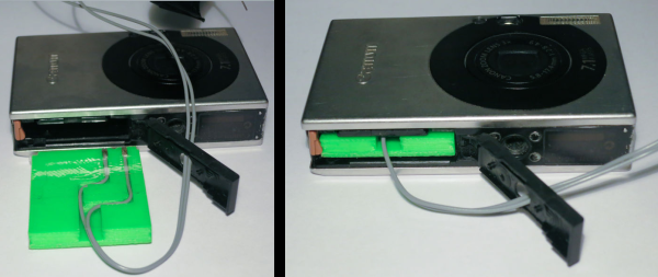
[Phil] decided to make a 3D printed battery emulator. It sits in place of the stock battery and holds bare wire where the batteries terminals normally are. The other end of the wires are run out of the camera to a voltage regulator that converts the battery pack’s 6 volts down to the 3.9 that the camera needs.

Continue reading “3D Printed Camera Battery Emulator”

Tweakie CNC Router

Home Made CNC Router Boasts Welded Steel Frame And Super Tidy Wire Management

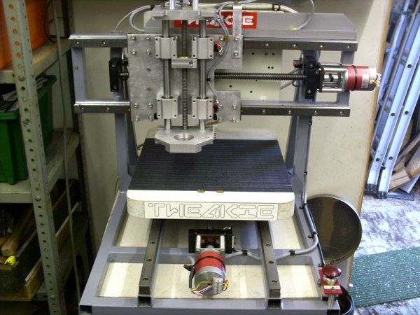
[Cooperman] had been poking around the ‘net checking out DIY CNC machines for a while. He wanted to build one. During his search, he noticed that there was a common thread amongst homemade machines; they were usually made from parts that were on hand or easily obtainable. He had some parts kicking around and decided to hop on the band wagon and build a CNC Router. What sets [Cooperman]’s project apart from the rest is that he apparently had some really nice components available in his parts bin. The machine is nicknamed ‘Tweakie‘ because it will never really be finished, there’s always something to tweak to make it better.

The foundation for Tweakie is a welded frame made from 25mm steel square tubing. A keen observer may point out that welding a frame may cause some distortion and warping. [Cooperman] thought of that too so he attached aluminum spacers to the steel frame and lapped them flat. After that, fully supported THK linear bearings were attached to the now-straight spacer surface. Both the X and Y axes have ball-screws to minimize backlash and are powered by NEMA23 stepper motors. The Z axis uses 16mm un-supported rods with pillow block linear bearings. Unlike the X and Y, the Z axis uses a trapezoidal lead screw and bronze nut. [Cooperman] plans on replacing this with a ball-screw in the future but didn’t have one on hand at the time of assembly.

Mach3 is the software being used to control the CNC Router. It communicates via parallel port with a 3-axis StepMaster motor driver board that can handle providing 24vdc to the stepper motors. All of the electronics are mounted neatly in an electrical cabinet mounted on the back of the machine. Overall, this is a super sturdy and accurate machine build. [Cooperman] has successfully cut wood, plastic and even aluminum!

Arduino Calculator

High Cost Arduino Calculator Is Unwieldy, Still Cool Though

One of [Kale_3D]’s teachers had made an Arduino-powered calculator. It wasn’t robust and didn’t last too long in the classroom environment. After the non-functional calculator sat around the class for a while, [Kale_3D] decided he would give a shot at repairing it. Along the way the project didn’t just get repaired, it got a full rebuild.

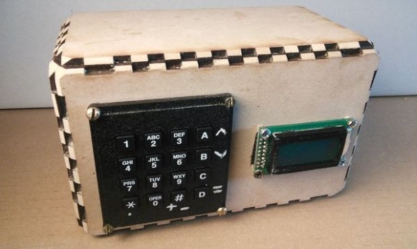
This calculator uses a full 16 button matrix keypad. The Arduino deciphers button pushes with the help of the Keypad library, at which time the appropriate character is displayed on the 2×8 LCD screen. Selecting the function is a little different from normal since this project is limited to 16 buttons. Two of the buttons allow scrolling through not only standard arithmetic functions but trigonometric functions also. This was one of the features that the previous version was not capable of.

To protect the components, an enclosure was made out of 1/4″ laser cut wood. The pieces have notched edges to permit a nice fit. Even so, corner blocks were added to give the case even more rigidity.

Yes, this calculator is not practical, but that’s not the point. In the end [Kale_3D] felt that the project was definitely worth doing. He had learned a bunch of stuff about Arduino and especially code debugging! Most important of all he had a good time building it. There’s a video after the break showing how it works. The code and wiring diagrams are available for download on the project’s Instructable page.

Continue reading “High Cost Arduino Calculator Is Unwieldy, Still Cool Though”

Simple Pen Plotter

Simple DIY Pen Plotter, Great First CNC Project

[Morten] has been busy recently making a pen plotter. It is a simple and elegant build that he completely designed from the ground up. There are no extra frivolous parts here. The frame is made from laser-cut plexiglass which makes fabrication easy if you have access to a laser cutter. Two NEMA17 motors are responsible for the machine’s movement. One moves the pen carriage back and forth by way of a belt. The other is connected by laser-cut gears to a roller bar, scavenged from an ink jet printer, that moves the paper media forward and aft underneath the pen.

The software chain used here is sort of uncommon compared to other inexpensive DIY CNC machines we see here on Hackaday. [Morten] creates his geometry with Rhino, then uses a plugin called Grasshopper to generate the g-code that controls the machine. That g-code is sent using gRemote to an Arduino flashed with the contraptor.org g-code interpreter. A RAMPS board takes the step and direction signals generated by the Arduino and moves the two stepper motors appropriately.

In typical open-supporting fashion, [Morten] has made his design files freely available for anyone to download. His plotter moves the pen side to side and the paper front to back in order to draw shapes but that’s not the only way a plotter can work. Check out this polar plotter and this one that hangs.

Check out the video after the break…

Continue reading “Simple DIY Pen Plotter, Great First CNC Project”

DIY Camera Shutter Control

Full SHTTTRRR Control Lets You Take Your Time…

[Glitchmaker] loves photography and wrote in to tell us about his newest project. He has a Canon 1000D camera but, unfortunately, it does not have time lapse capability. So, instead of shelling out a chunk of change for a new camera [Glitchmaker] decided to make an external shutter control device that can continue to instruct the camera to take photos at predetermined intervals. He calls his project: SHTTTRRR. You didn’t think that meant something else, did you?

You can see the unassuming box above, there is just enough stuff packed in there to get the job done, nothing extra or fancy. Luckily, the Cannon camera has a remote shutter input jack that only requires connecting one pin to another in order to take a photo. Inside the box is an ATTINY45 microcontroller. It reads the button pushes from the single panel-mounted button and calculates the time between two button presses. That time between button presses determines the frequency of the photos taken. At the appropriate times, the ATTINY45 signals a transistor to connect the two appropriate pins on the camera’s remote shutter input jack. The device continues to tell the camera to take photos until it is shut off. The result is a series of time-lapse photos that was previously not possible on that camera!

This is a simple project that solves a problem and gets the job done. What’s better than that? [Glitchmaker] is proud of the SHTTTRRR he made and also learned a bunch about programming the ATTINY45 along the way. Check a video of it working after the break.

Continue reading “Full SHTTTRRR Control Lets You Take Your Time…”

solar cell saw

Automated Table Saw Cuts Photovoltaic Solar Cells

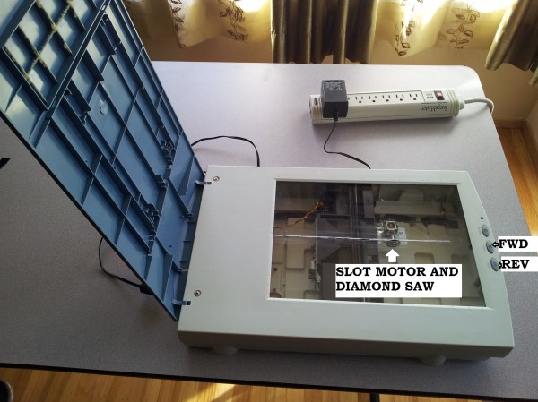
[sudarshan] is a solar hobbyist and needed a way to cut solar cells for his projects. He had previously created a rotary tool saw but manually feeding them through was sketchy at best. With just a slight wrong movement of his hand or flex in the work surface would cause the cell to break. These cells are extremely brittle and break easily. He needed a method of cutting these cells that was free from jitters and would cut in a straight line. He looked around his junk bin and found an odd solution… a scanner. Yes, the type you would scan photos in your computer with. The scanner had two critically important features, a flat surface and a carriage mechanism that moves perfectly parallel with that flat surface.

[sudarshan] made a solar cell cutting mini table saw with that scanner and made the cutting happen automatically. He mounted a motor with a diamond saw disk to the carriage, that is responsible for the cutting. The blade was positioned just high enough to poke through the plexiglass that replaced the original glass bed. A power switch turns on the cutting disk motor and an Arduino was used to move the carriage, including the cutting blade, back and forth. Two of the stock scanner buttons were reused and wired to the Arduino to keep the saw looking good.

The first few passes of the saw were done to cut a slot in the plexiglass. In order to cut a solar cell, the cell is taped to the bed with the desired cut location aligned with the slot in the plexiglass bed. Once everything is set, hit the ‘go’ button and the saw blade is slowly pushed through the cell, leaving a straight, clean cut.

Continue reading “Automated Table Saw Cuts Photovoltaic Solar Cells”

Mini EV Tractor

Odd-Looking Mini EV Yard Tractor Is Made From Plywood And Bike Parts

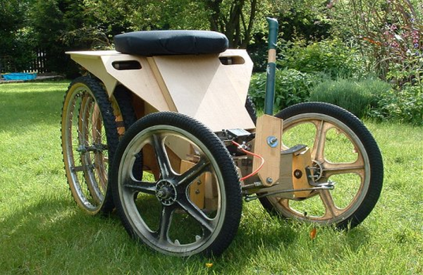
Mini EV Tractor[Ian] likes to build small Electric Vehicles and his most unique project is certainly this yard tractor. During the design phase of the project [Ian] came up with a few requirements to ensure that this vehicle would be useful around the house. First, it had to be maneuverable in tight spaces. This was accomplished by the short wheel base and small diameter front-steering wheels. Next, it had to get great traction as leaving torn-up grass around the yard was not going to cut the mustard. Four mountain bike drive wheels used in the rear double the traction while at the same time distributing the friction over twice the surface area of the grass. To increase the traction even more, the rider’s seating position was intentionally put directly over the rear wheels.

The frame was kept simple by using plywood as structural members. Two 40Ah 12v batteries are set low between the front and rear axles and power the 4 DC drive motors. The motors are connected to the axle by means of sprockets and chains which results in a 36:1 reduction. That’s a large gear reduction and limits the tractor to a top speed of 12 km/h (7.5 mph). Bike tires front and rear were used because they are easily available and are super low-cost. And of course, a tractor wouldn’t be complete without a trailer hitch to tow around plants, rocks, wood or any other general yard debris.

[Ian] makes plans for his mini EV tractor available on his website. If your kid is envious of this electric tractor, maybe you can make him one of these