Simple FM Transmitter That Shows Off Its Own Circuitry

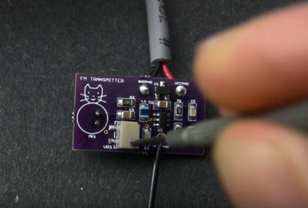
[Sean Michael Ragan] built this FM transmitter which shows off its circuitry via a clear plastic dome. The device is electrically identical to one we looked at in September. That version championed a construction method that used small squares of copper clad as solder points which were each super-glued to a large copper-clad platform serving as a ground plane. [Sean] is using a printed circuit board that was laid out by Sonodrome. You can check out their own glass-jar transmitter build where the board artwork is available for download.

One of the tips we enjoyed from [Sean’s] step-by-step build is the coil wrapping. He used the threads of a 1/4-20 bolt to guide copper wire as he wrapped a total of four turns. Once the bending is done, just unthread the bolt to separate it from the coil and gently stretch the wire for a 12mm distance between the two leads. Not only is this visually pleasing, but it will help with transmission clarity.

Minty FM Transmitter

[Chis] wanted an FM transmitter bug device packed in a mint tin, and that is just what he made. Featuring only 17 discrete parts, running off of a 3volt coin cell battery, and small enough to fit inside of a plastic mint box and still have plenty of room for the mints.

Using a simple design the audio enters the device through a electret microphone and hits a transistor for amplification, the signal is then passed to the oscillator section of the circuit which features an LC tank type design which generates the carrier frequency and mixes that with the signal for a range of about 100 feet indoors.

Each section is broken down into steps where it is thoroughly explained with animations, theory, and simulation, if you are wondering how a transistor, wire, and capacitors make an FM transmitter, or if you would like to just make the final project, schematics, pcb files, and assembly instructions are provided as well.

Join us after the break for a short video and be sure to check out the other radio transmitters we have featured as well.

Continue reading “Minty FM Transmitter”

Tiny FM Transmitter Bugs Rooms

Lucid Science delves into spy-tech once again with this tiny FM transmitter. Their post demonstrates a bit larger version than seen above, using a 9-volt battery and protoboard sized to match which makes for easier soldering. The design uses a microphone, two transistors, enameled wire for the coil, as well as various resistors, capacitors, and a potentiometer. What you end up with is an amazingly clear audio signal that can be picked up with a normal FM radio.

This would make a great project to do with the kids. You can talk about circuit design, practice soldering, and when finished they’ve got an almost miraculous toy to play with. Just be careful what you say around the house, the room might be bugged!

A Simple FM Transmitter

Here is a low component count FM transmitter. It sacrifices some features, like the ability to adjust the frequency, for simplicity’s sake. The build method is fairly common with amateur radio but we don’t see it around here too much. Each component gets a 5mm-by-5mm copper clad pad which is super glued to the ground plate as an insulator. There’s even a pictorial example of this method if you need some help with visualization.

One of the schematics included in the article shows how to incorporate a condenser microphone into the unit. We guess that makes it pretty easy to add an FM ‘bug’ to your arsenal of covert listening devices. Just make sure to check your local laws before building and using this. We’re not sure what the FCC would think of it here in America so we’re hoping some well-informed readers will educate us with a comment.

[Thanks Bart]

FM 101 And Transmitter Build With Afroman

One of our favorite purveyors of electronics knowledge is at it again. This time, [Afroman] explains how frequency modulation works while building up a short-range FM transmitter on a board he has available at OSH Park.

The design is based on a MAX2606 voltage-controlled oscillator (VCO) chip that can do 70-150MHz. [Afroman] sets it up to oscillate at about 100MHz using a 390nH inductor. He also put a potentiometer voltage divider on the 2606’s tuning pin. Voltage changes issued through the pot alter the transmitting frequency in small increments, making it easy to dial in a suitable channel for your broadcast. Add an electret mic and about a meter’s worth of solid-core wire and you have yourself an FM transmitter that is good for around 20 meters.

There are plenty of ways to build a small FM transmitter that allow for some experimentation and don’t involve placing SMD components. We covered a build last summer that uses a couple of 3904s and rides a 9V connector salvaged from a dead battery. The downside is that transistor-based transmitters tend to be less frequency-stable than a VCO chip.

Continue reading “FM 101 And Transmitter Build With Afroman”

FM Stereo Transmitter

Reader [Mike Y] responded to our “What are you working on?” post  with his stereo FM transmitter project. If you’ve ever used an FM transmitter for your portable audio, you know that even the best consumer level ones can be difficult to make sound decent.

He obtained an NS73M FM Transmitter module from Niigata Seimitsu Company, but it required a controller to handle pre-emphasis, modulation level, frequency, and power level. He decided on an Arduino which would also control his LCD.

His results were quite good, with decent range and superb audio quality. His total cost thus far is $35, but he still needs to put it in an enclosure. You can find complete schematics as well as source code and helpful tips on his site.  You may also want to check out the regulations on broadcasting(pdf) as well.

How The BBC (Still) Sends Audio To Transmitter Sites

Running a radio station is, on the face of it, a straightforward technical challenge. Build a studio, hook it up to a transmitter, and you’re good to go. But what happens when your station is not a single Rebel Radio-style hilltop installation, but a national chain of transmitter sites fed from a variety of city-based studios? This is the problem facing the BBC with their national UK FM transmitter chain, and since the 1980s it has been fed by a series of NICAM digital data streams. We mentioned back in 2016 how the ageing equipment had been replaced with a modern FPGA-based implementation without any listeners noticing, and now thanks to [Matt Millman], we have a chance to see a teardown of the original 1980s units. The tech is relatively easy to understand from a 2020s perspective, but it still contains a few surprises.

In each studio or transmitter site would have been a 19″ rack containing one of these units — a card frame with a collection of encoder or decoder cards. These are all custom-made by the BBC’s engineering department to a very high standard, and use period parts such as the familiar Z80 microprocessor and some Philips digital audio chips, which followers of high-end consumer audio may recognize. As you’d expect for a mission critical device, many of the functions are duplicated for redundancy, with their outputs compared to give warning of failures.

The surprise comes in the NICAM encoder and decoder — it’s a custom LSI chip made exclusively for the BBC. This indicates the budget available to the national broadcaster, and given that these units have in some cases been working for over 35 years, we’re guessing that the license payers got their money’s worth.

You can read about the original switch-over in 2016, and a little more about NICAM, too.