Here’s another very interesting project to come out of the 4 Minute Mile challenge — pneumatically boosted legs.
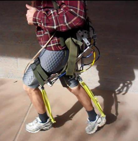
It’s another project by [Jason Kerestes] in cooperation with DARPA. We saw his jet pack a few days ago, but this one looks like it has a bit more promise. It is again a backpack mounted system, but instead of a few jet turbines, it has a pneumatic cylinders which move your legs for you.
Just watching it it’s hard to believe it makes it easier to run, but apparently after being tested at the Army Research Laboratories last year it demonstrated a whopping 10% reduction in metabolic cost for subjects running at high speeds. It can actually augment the human running gait cycle, and is the only device the US Army has confirmed can do so.
He is already hard at work designing version 2.0 which is lighter and more flexible. There’s a bunch of test videos after the break so stick around to see it in action.