Re-imagining The Crossed Gantry 3D Printer

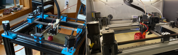
Simply having a few go-to 3D printer motion system designs is no reason to stop exploring them, as even small iterations on an existing architecture can yield some tremendous improvements. In the last few months, both [Annex_Engineering] and [wesc23] have been piloting a rail-derived crossed gantry architecture, a “CroXY” as it’s come to be known. Borrowing concepts from Ultimaker’s crossed gantry using rods, the Hypercube Overkill project, and perhaps even each other, the results are two compact machine frames capable of beautiful prints at extremely high speeds–upwards of 400 mm/sec in [Annex_Engineering’s] case!

Both gantry designs take a rotated MGN12 rail (a la the Railcore) and cross two of them, mounting the carriage at the intersection point much like an Ultimaker. Each crossed rail controls a degree of freedom with vanilla Cartesian kinematics, but each degree of freedom also has a redundant motor for added torque. Like the CoreXY design, this setup is tailored for clean prints at high speeds since the motion-related motors have been removed from the moving mass. However the overall belt length has been reduced tremendously, resulting in a much stiffer setup.

But the innovation doesn’t stop there. Both gantries also feature a unique take on a removable Z probe. When the machine needs to level the bed, it travels to a corner to “quickdraw” a magnetically attached limit switch from a holster. Once mounted, this probe becomes the lowest point on the carriage, allowing the carriage to travel around the bed probing points. When finished, the probe simply slots back into its holster, and the print can begin.

Both [wesc23’s] CroXY and a variant of [Annex_Engineering’s] K2 are up on Github complete with bills of materials if you’re curious to poke into the finer details. With commercial 3D printer manufacturers spending the last few years in a race to the bottom, it’s exciting to still see new design pattern contributions that push for quality and performance. For more design patterns contributions, have a look at [Mark Rehorst’s] Kinematically coupled bed design.

Continue reading “Re-imagining The Crossed Gantry 3D Printer”

Printing, Plating, And Baking Makes DIY Microlattices Possible

To be honest, we originally considered throwing [Zachary Tong]’s experiments with ultralight metallic microlattices into the “Fail of the Week” bucket. But after watching the video below for a second time, it’s just not fair to call this a fail, so maybe we’ll come up with a new category — “Qualified Success of the Week”, perhaps?

[Zachary]’s foray into the strange world of microlattices began when he happened upon a 2011 paper on the subject in Science. By using a special photocurable resin, the researchers were able to use light shining through a mask with fine holes to create a plastic lattice, which was then plated with nickel using the electroless process, similar to the first half of the electroless nickel immersion gold (ENIG) process used for PCBs. After removing the resin with a concentrated base solution, the resulting microlattice is strong, stiff, and incredibly light.

Lacking access to the advanced materials and methods originally used, [Zachary] did the best he could with what he had. An SLA printer with off-the-shelf resin was used to print the skeleton using the same algorithms used in the original paper. Those actually turned out pretty decent, but rather than electroless plating, he had to go with standard electroplating after a coat of graphite paint. The plated skeletons looked great — until he tried to dissolve the resin. When chemical approaches failed, into the oven went the plated prints. Sadly, it turns out that the polymers in the resin expand when heated, which blew the plating apart. A skeleton in PLA printed on an FDM printer fared little better; when heated to drive out the plastic, it became clear that the tortuous interior of the lattice didn’t plate very well.

From aerogels to graphene, we love these DIY explorations of new and exotic materials, so hats off to [Zachary] for giving it a try in the first place.

Continue reading “Printing, Plating, And Baking Makes DIY Microlattices Possible”

E3D Teaches Additive 3D-Printers How To Subtract

We might’ve thought that extrusion based 3D printers have hit their peak in performance capabilities. With the remaining process variables being tricky to model and control, there’s only so much we can expect on dimensional accuracy from extruded plastic processes. But what if we mixed machines, adding a second machining process to give the resulting part a machined quality finish? That’s exactly what the folks at E3D have been cooking up over the last few years: a toolchanging workflow that mixes milling and 3D printing into the same process to produce buttery smooth part finishes with tighter dimensional accuracy over merely 3D printing alone.

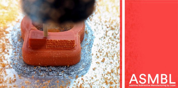
Dubbed ASMBL (Additive/Subtractive Machining By Layer), the process is actually the merging of two complimentary processes combined into one workflow to produce a single part. Here, vanilla 3D printing does the work of producing the part’s overall shape. But at the end of every layer, an endmill enters the workspace and trims down the imperfections of the perimeter with a light finishing pass while local suction pulls away the debris. This concept of mixing og coarse and fine manufacturing processes to produce parts quickly is a re-imagining of a tried-and-true industrial process called near-net-shape manufacturing. However, unlike the industrial process, which happens across separate machines on a large manufacturing facility, E3D’s ASMBL takes place in a single machine that can change tools automatically. The result is that you can kick off a process and then wander back a few hours (and a few hundred tool changes) later to a finished part with machined tolerances.

What are the benefits of such an odd complimentary concoction, you might ask? Well, for one, truly sharp outer corners, something that’s been evading 3D printer enthusiasts for years, are now possible. Layer lines on vertical surfaces all but disappear, and the dimensional tolerances of holes increases as the accuracy of the process is more tightly controlled (or cleaned up!) yielding parts that are more dimensionally accurate… in theory.

But there are certainly more avenues to explore with this mixed process setup, and that’s where you come in. ASMBL is still early in development, but E3D has taken generous steps to let you build on top of their work by posting their Fusion 360 CAM plugin, the bill-of-materials and model files for their milling tool, and even the STEP files for their toolchanging motion system online. Pushing for a future where 3d printers produce the finer details might just be a matter of participating.

It’s exciting to see the community of 3D printer designers continue to rethink the capabilities of its own infrastructure when folks start pushing the bounds beyond pushing plastic. From homebrew headchanging solutions that open opportunity by lowering the price point, to optical calibration software that makes machines smarter, to breakaway Sharpie-assisted support material, there’s no shortage of new ideas to play with in an ecosystem of mixed tools and processes.

Have a look at ASMBL at 2:29 in their preview after the break.

Continue reading “E3D Teaches Additive 3D-Printers How To Subtract”

Quick 3D-Printed Airfoils With These OpenSCAD Helpers

You know how it is. You’re working on a project that needs to move air or water, or move through air or water, but your 3D design chops and/or your aerodynamics knowledge hold you back from doing the right thing? If you use OpenSCAD, you have no excuse for creating unnecessary turbulence: just click on your favorite foil and paste it right in. [Benjamin]’s web-based utility has scraped the fantastic UIUC airfoil database and does the hard work for you.

While he originally wrote the utility to make the blades for a blower for a foundry, he’s also got plans to try out some 3D printed wind turbines, and naturally has a nice collection of turbine airfoils as well.

If your needs aren’t very fancy, and you just want something with less drag, you might also consider [ErroneousBosch]’s very simple airfoil generator, also for OpenSCAD. Making a NACA-profile wing that’s 120 mm wide and 250 mm long is as simple as airfoil_simple_wing([120, 0030], wing_length=250);

If you have more elaborate needs, or want to design the foil yourself, you can always plot out the points, convert it to a DXF and extrude. Indeed, this is what we’d do if we weren’t modelling in OpenSCAD anyway. But who wants to do all that manual labor?

Between open-source simulators, modelling tools, and 3D printable parts, there’s no excuse for sub-par aerodynamics these days. If you’re going to make a wind turbine, do it right! (And sound off on your favorite aerodynamics design tools in the comments. We’re in the market.)

Single Piece 3D-Printed PCB Vise

Making full use of the capabilities and advantages of 3D printing requires a very different way of thinking compared to more traditional manufacturing methods. Often we see designs that do not really take these advantages into account, so we’re always on the lookout for interesting designs that embrace the nature of 3D-printed parts in interesting ways. [joopjoop]’s spring-loaded PCB vise is one such ingenious design that incorporates the spring action into the print itself.

This vise is designed to be printed as a single piece, with very little post-processing required if your printer is dialed in. There is a small gap between the base plate and the springs and clamping surfaces that need to be separated with a painters knife or putty knife. Two “handles” have contours for your fingers to operate the clamping surfaces. It opens quickly for inserting your latest custom PCB.

PLA can be surprisingly flexible if the right geometry is used, and these springs are an excellent example of this. In the video below [Chuck Hellebuyck] does a test and review of the design, and it looks like it works well for hand soldering (though it probably won’t hold up well with a hot air station). Last month our own [Tom Nardi] recently reviewed a similar concept that used spiral springs designed into the printed part. While these both get the job done, [Tom’s] overall verdict is that a design like this rubber-band actuated PCB vise is a better long-term option.

It takes some creativity to get right, but printing complete assemblies as a single part, is a very useful feature of 3D printing. Just be careful of trying to make it the solution for every mechanical problem.

Tensile Testing Machine Takes 3D Printed Parts To The Breaking Point

If you’re serious about engineering the things you build, you need to know the limits of the materials you’re working with. One important way to characterize materials is to test the tensile strength — how much force it takes to pull a sample to the breaking point. Thankfully, with the right hardware, this is easy to measure and  [CrazyBlackStone] has built a rig to do just that.

Built on a frame of aluminium extrusion, a set of 3D printed parts to hold everything in place. To apply the load, a stepper motor is used to slowly turn a leadscrew, pulling on the article under test. Tensile forces are measured with a load cell hooked up to an Arduino, which reports the data back to a PC over its USB serial connection.

It’s a straightforward way to build your first tensile tester, and would be perfect for testing 3D printed parts for strength. The STEP files (13.4 MB direct download) for this project are available, but [CrazyBlackStone] recommends waiting for version two which will be published this fall on Thingiverse although we didn’t find a link to that user profile.

Now we’ll be able to measure tensile strength, but the stiffness of parts is also important. You might consider building a rig to test that as well. Video after the break.

Continue reading “Tensile Testing Machine Takes 3D Printed Parts To The Breaking Point”

A High Torque Gearbox You Can Print At Home

Typically, when we think of 3D printed parts, we think of unique parts with complex geometries that would be hard to fabricate with other techniques. Strength is rarely the first thing that comes to mind, due to the limitations of thermoplastics and the problem of delamination between layers. However, with smart design, it’s possible to print parts capable of great feats, just as [Brian]’s high-torque gearbox demonstrates.

Pulling a car is a great way to show off the strength of your build.

The gearbox consists of entirely 3D-printed gears, along with the enclosure, with the only metal parts being a few bearings and shafts. Capable of being produced out of PLA on a regular FDM printer, [Brian] has successfully tested the gearbox up to 132 kg∗cm. The suspicion is that there may be more left in it, but some slippage was noticed in the gear train when trying to tow a Ford Focus with the handbrake still on.

Even better, with the addition of a potentiometer, the gearbox can be used as an incredibly tough servo. [Brian] demonstrates this by lifting 22 kg at a distance of 6 cm from the center of the output shaft. The servo does it with ease, though eventually falls off the bench due to not being held down properly.

It’s a build that shows it’s possible to use 3D-printed parts to do some decently heavy work in the real world, as long as you design appropriately. [Brian] does a great job of explaining what’s involved, discussing gear profile selection and other design choices that affect the final performance. We’ve seen similar work from others before, too. Video after the break.

Continue reading “A High Torque Gearbox You Can Print At Home”