Ask Hackaday: How About Some Model Rocket Hacks?

There’s nothing like the smell of black powder in the morning, along with the excitement and burnt propellant in the air that comes after launching a model rocket. All those 60s, 70s, 80s and 90s kids out there may remember the classes of model rocket engines – generally A, B, C, and D sized engines used to push your cardboard tube with balsa fins skyward.

A lot has changed in the world of model and amateur rocketry in the last few years. In 2009, the Tripoli Rocketry Association won a lawsuit against the Bureau of Alcohol, Tobacco, Firearms and Explosives to allow the sale of Ammonium perchlorate rocket engines to anyone. This lawsuit took almost 10 years to come to a head, but finally anyone can walk into Hobby Lobby and come out with D, E, F, and G engines in hand. Even our old favorite, Estes rockets, has gotten into the game by putting out a few awesome G-powered kits. With these off-the-shelf motors, anyone (in the US, at least) can launch a G-powered model rocket weighing under 1500 grams (3.3 lbs) without the need for a certification.

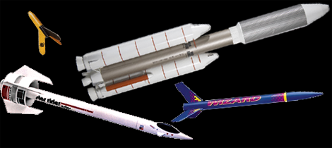
With that in mind, we’re putting out a call for model rocket hacks. If you put together an microcontroller-powered altimeter project, awesomeSend it in. On board video camera? Great! Even if you built a huge replica of the Titan IIIe (or the Estes Star Rider, a personal favorite), send that thing in. If you’re going for a huge Saturn V, the record to beat is a 1/10 scale model, so get on it.

Ask Hackaday: Who Wants To Build A Function Generator?

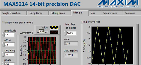
[tari] sent in a tip about a MAX5214 DAC evaluation board AVNET is giving away this summer.  The MAX5214 / MAX5216 is a neat little chip providing a 14 or 16 bit DAC with a serial interface in a tiny 8-pin package. [tari] thinks this eval board could be hacked into a function generator, and we’ve got to agree. Now, who wants to build one?

It’s entirely possible to take the MAX5214 chip and put it in a circuit with a small ARM uC, a display, and a few knobs, but that seems like a waste of time given function generators of this caliber are already available for about $60. It seems the most efficient hack of this dev board will be simply adding an amplifier to this board’s output and possibly programming a better interface than the current LabView software available.

If you want to tinker around with some free hardware and make something useful in the process, have a go at making a function generator out of this dev board. Be sure to send it in when you’re done.

Ask Hackaday: Has Anyone Built A Radio Telescope?

[Michael] sent in a question regarding the latest advances in software defined radios available for $20 on eBay:

I’ve been looking in to SDR lately, mainly for the possibility of using it for incredibly cheap radio astronomy. So far all I’ve found are whispers. I’m 18 and have very little experience, but I figured you might be able to help me find a little more info.

This really brings me back, [Michael]. I saw Contact in the theater (surprisingly, a rare case when the book and movie are equals), and in my childish exuberance went out and listened to lightning on Jupiter. The financial difficulties of expanding my setup meant the experiments stopped there, but at least I knew amateur radio telescopy was possible.

The latest and greatest advance in software defined radio – namely, a $20 TV tuner dongle – brings something new to the table. Instead of the thousands of dollars in gear that was required in 1997 when I last looked into this, it’s possible to set up a  passable radio telescope for under $100.

I’ll leave it to the Hackaday commentors to fill [Michael] in on the details, but here’s my suggestion:

Optimize your setup for 1420 MHz. There are three reasons for this: firstly, very few things in the universe absorb radio waves at a frequency of 1420MHz; there’s a reason it’s so often used in radio astronomy. Secondly, most government agencies around the world ban (or at least don’t look too kindly upon) transmitting on 1420 MHz. This frequency has been somewhat protected for use by astronomers. Thirdly, most of the Realtek TV tuner dongles have a frequency range of 64 – 1700 MHz, so it’s possible to receive 1420 MHz with this minimal setup.

As far as antennas go, your best bet is probably going to be one of those old C-band parabolic antennas from the 80s. That will make your telescope highly directional and give it a huge amount of gain. There is the problem of having a 20-foot-wide eyesore in your back yard, however. Alternatively, you could use a smaller DirecTV satellite dish, but I’m not making any promises with that. It’ll work, but it’s too small for an optimal setup.

I’ll concede the floor to anyone who has additional information. If you’ve built a radio telescope, send it in and I’ll put it up.

Ask Hackaday: Troll Physics Super Deluxe Edition

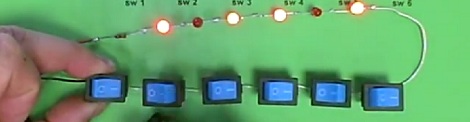
Here’s a brain bender for you: YouTube user [Fredzislaw100] put up a video of six LEDs and six switches wired up in series. After soldering a resistor and 9V battery connector, the first switch turns on the first LED, the second switch turns on the second LED, and so on for the rest of the circuit.

We’ve seen this trick before from [Fredzislaw100], only this time he’s moved up from 3 LEDs to 6. In the reveal of the previous trick, [Fredzislaw] built two AC power supplies inside a nine volt battery connector; one high frequency and one low frequency. The low frequency AC line powers the first two LEDs with the help of diodes in the switches and LEDs. The high frequency AC line turns on the third LED with the help of an inductor inside an LED. Apparently [Fredzislaw] still has some soldering skills to show off; the circuit powering this trick is most likely the work of a soldering god.

From a close viewing, it looks like LEDs are wired up in pairs, i.e. LED 1 works the same as LED 2, LED 3 works the same as LED 4, etc. We’ll let Hackaday readers argue it out in the comments as to how this trick is possible.

Tip ‘o the hat to [Th0m4S] for sending this one in.

The Pi Pad

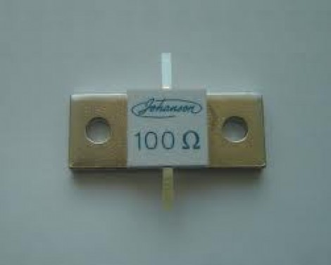
In the world of electronics we have impedance; the combination of all forces which oppose the flow of electric current. Often times we have circuits with different impedances, 50 ohms for RF, or 75 for cable TV. It’s pretty important to use the right coax in these circuits, else you’ll be wondering why your RG-58 antenna feed line doesn’t give you anything good to watch.

It’s pretty important to match impedances when connecting different circuits. Apart from the obvious flaws such as a 50 ohm load blowing up a 300 ohm amplifier, there are subtler things such as signal reflection and destructive interference which might just be enough to break whatever it is your playing with. RF mosfets are not cheap! But how could we match impedances? Well we could always use a transformer, but those are rather expensive and bulky. What if we only have a box of resistors to play with? Continue reading “The Pi Pad”

Ask Hackaday: Building Nano Scale Antennas

As an RF engineering student, [Camerin] is usually tasked with pointless yet educational endeavors by his advisor and professors. Most of the time (we hope) he sees the task through and ends up pulling something out of his hat, but a few days ago a professor dropped a bombshell on him. After reading this article on nano scale antenna fabrication, a professor asked [Camerin] if it was possible to build a 3D inkjet printer with a ludicrous amount of accuracy and precision.

The full article, Conformal Printing of Electrically Small Antennas on Three-Dimensional Surfaces, was recently published in Advanced Materials and is available via Google Scholar. The jist of the article is that three-dimensional antennas printed on a sphere approach the physical limits of how good an antenna can be. To test out these small, spherical antennas, the authors of the paper built an extremely high-precision 3D inkjet printer that draws antenna traces on a glass sphere with conductive ink.

The positional accuracy of this printer is 50 nanometers, or about half the size of an HIV virus. The conductive silver ink is delivered by a nozzle with a diameter of 100 to 30 µm and prints onto a glass sphere about 6 mm in diameter. This is a level of precision that companies and research institutions pay top dollar for, so we’re left wondering how the authors built this thing.

We’re turning this question over to the astute readers of Hackaday: how exactly would you build a 3D inkjet printer with this much accuracy and precision? Would it even need to be that precise? Post your answer in the comments.