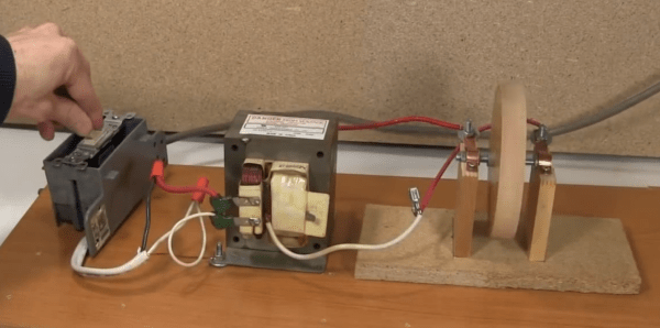
A Retro, Not Steampunk, Media Center

[toddfx] wanted to put his Raspberry Pi to work and set about creating one of the best stereos we’ve ever seen: It’s called the Audio Infuser 4700, and turns a conglomeration of old disused stereo equipment into a functional piece of art.

[toddfx] used a Raspberry Pi to stream music over WiFi, but also wanted to play some classic vinyl. He took apart an old Yamaha YP-D4 turntable. stripped it to the bone, and created a fantastic oak enclosure around it. To this, he added a seven-band graphic EQ, aux jacks (both in and out), and a tiny 5″ CRT from an old portable TV.

Where this build really gets great is the fabrication. The front panels have all their graphics and lettering engraved via a toner-transfer like method using copper sulphate and salt. [todd] got the idea from this thread and we have to say the results are unbelievable.

Even though this awesome device only used for music, [toddfx] used the tiny color CRT to its fullest. Flick one switch, and it’s an oscilloscope-like display. Flick another switch, and it’s the output of the Raspberry Pi loaded up with a few MAME games including Pacman, Asteroids, and Space Invaders.

[toddfx] put up a build page for his Audio Infuser and an awesome video for his project, available below.

Continue reading “A Retro, Not Steampunk, Media Center”

5 Digit Security Code Activated Relay Using Mostly Discrete Circuitry

alarm keypad

Let’s rollback the hobby electronics calendar a few decades with [myvideoisonutube’s] alarm activation control circuit using a matrix style phone keypad. The circuit is quite old using CMOS 4081 with 4 ‘AND’ gates to hardwire the access code. [myvideoisonutube] references [Ron’s] “Enhanced 5-Digit Alarm Keypad” schematic for this build changing the recommend keypad with a more common matrix style keypad found in touch pad phones. These types of matrix keypads wouldn’t work outright for the input so he cut some traces and added hookup wires to transform it into a keypad with common terminals and separately connected keys. We love seeing such hacked donor hardware even when it requires extensive modifications. [Ron’s] source circuit included a simple enough to build tactical button keypad if you can’t find a suitable donor phone.

Learning how to use mostly discrete components instead of a microcontroller would be the core objective to build this circuit outside of needing a key-code access point or other secure 12 V relay activated device. Such a device would be quite secure requiring a 4 digit “on” code and 5 digits for “off”. You couldn’t just pull off the keypad and hotwire or short something to gain access either. The 4 digit on “feature” does knock the security down quite a lot. However, all keys not in the access code are connected to the same point so you could increase your security by using a pad with more keys.

On [Ron’s] site you will find a detailed construction guide including top and bottom view for placement of all the components on veroboard. Join us after the break to watch [myvideoisonutube] demo his version.

Continue reading “5 Digit Security Code Activated Relay Using Mostly Discrete Circuitry”

Inside The Clapper

clapper

Hackaday readers above a certain age will probably remember the fabulously faddish products developed by Joseph Enterprises. These odd gadgets included the Ove’ Glove, VCR Co-Pilot, the Creosote Sweeping Log, and Chia Pet (Cha-Cha-Cha-Chia) as mainstays of late night commercials, but none were as popular as The Clapper, everyone’s favorite sound-activated switch from the 1980s. [Richard] put up a great virtual teardown of The Clapper, that provides a lot of insight into how this magic relay box actually works, along with some historical context for the world The Clapper was introduced to.

Sound activated switches are nothing new, but the way The Clapper did it was just slightly brilliant. Instead of listening to every sound, the mic inside the magic box sends everything through a series of filters to come up with a very narrow bandpass filter centered around 2500 Hz. This trigger is analyzed by a SGS Thompson ST6210 microcontroller ( 4MHz, ~1kB ROM, 64 bytes of RAM, and 12 I/O pins ) to listen for two repeating triggers  within 200 milliseconds. The entire system – including the source code for the MCU – can be seen in the official patent, US5493618.

The Clapper sold many millions of units at a time when a lot of homes were assuredly in a pre-microelectronics world. Yes, in 1986, a lot of TVs had microcontrollers and maybe a washer/dryer combo may have had a few thousand transistors between them. Other than that, The Clapper was many household’s introduction to the ubiquitous computing power we see today, and all with less capability than an Arduino.

Homebuilt 30kV High Voltage Power Supply

If you have need for 30,000 volts to launch your ionocraft (lifter) or power other DIY projects then shuttle over to RimstarOrg’s YouTube channel and checkout [Steven Dufresne’s] homebuilt 30kV power supply. The construction details that [Steven] includes in his videos are always amazing, especially for visual learners. If you prefer text over video he was kind enough to share a schematic and full write up at rimstar.org.

The power supply can be configured for 1.2kV – 4.6kV or 4kV – 30kV at the output while requiring 0-24V DC at the input. In the video [Steven] tries two power supplies. His homemade DC bench power supply at 8V and 2.5A and also a laptop power supply rated at 20V 1.8A DC. A couple of common 2N3055 power transistors, proper wattage resistors, a flyback transformer and a high voltage tripler is about all you’ll need to scrounge up. The flyback transformer can be found in old CRT type televisions, and he does go into details on rewinding the primary for this build. The high voltage tripler [Steven] references might be a bit harder to source. He lists a few alternates for the tripler but even those are scarce: NTE 521, Siemens 76-1 N094, 1895-641-045. There are lots of voltage multiplier details in the wild, but keep in mind this tripler needs to operate up to 30kV.

Join us after the break to watch the video and for a little advice from Mr. Safety.

Continue reading “Homebuilt 30kV High Voltage Power Supply”

What’s Inside A 555?

555

The 555 timer chip is a ubiquitous piece of technology that is oft-considered the hardcore way of doing things. Of course, the old timers out there will remind us that discrete transistors are the badass way of doing things, and tubes even more so. It’s not quite at the level of triodes and transformers, but Evil Mad Scientist’s discrete 555 kit is still an amazing piece of kit.

Instead of transistors and resistors etched into silicon as in the OG 555, [Windell] over at EMS turned the basic circuit inside a 555 into a mega-sized version using discrete components. Your parts bins need new scale if you’re going to work with this and other up-scaled hobby electronic components.

Although the integrated stand that makes the whole package look like an overgrown DIP doesn’t break out the signals on the board, it does include some neat screw terminals for alligator clips and bits of wire so this kit can be used in a circuit. Because it uses discrete components, you can also take a meter or scope to check out how a 555 chip works from the inside.

The Easy Or Hard Way To Build A PWM Dimmer

From what you would gather from Hackaday’s immense library of builds and projects over several years, the only way to do PWM is with a microcontroller, some code, a full-blown IDE, or even a real-time operating system. To some readers, we’re sure, this comes naturally and with an awesome toolchain it can be as easy as screwing in a light bulb. There is, of course, an easier way.

[Jestin] needed to vary the current on a small 12 Volt load. Instead of digging out an in system programmer, he turned to the classic 555 chip. With a single pot, it’s easy to vary the duty cycle of the 555 and connect that to a MOSFET. Put a load in there, and you have a very easy circuit that’s a fully functioning PWM dimmer.

If all you have are a few scraps in your part drawers, this is a very, very easy way to set up a dimmer switch. We’re also loving [Jestin]’s improv aluminum tube enclosure, as seen in the video below.

Continue reading “The Easy Or Hard Way To Build A PWM Dimmer”

The Nibbler: A 4-bit CPU Built With 7400 Logic

nibbler-schematic

Maybe we shouldn’t say “built” since [Steve Chamberlin] hasn’t actually heated up his iron yet. From the finished schematic above that is puzzling at first, until you realize the scope of the project. His Nibbler implements a 4-bit CPU using 7400 logic chips. Because he’s come up with the architecture himself he’s taking a lot of steps to check all of his work before committing to a PCB.

We linked to his category for the project which is still in progress. Most recently he wrote a program to prove that it’ll run on the hardware. That’s a feat considering this is still just a design idea. It was made possible because he wrote a simulator based on the design. The C++ tool simulates data and control buses and features a full set of debugging tools.

Careful testing of the design before the build is the best possible way to go. The simulator and debugging tools will be useful for software development even after the hardware is built. And testing before wiring is a must as these things get out of control quickly in terms of soldering complexity.

[via Dangerous Prototypes]