We Would Not Want To Be Stormtroopers Right Now

Humanity is another step closer to a fantasy-accurate lightsaber thanks to Hackaday alumnus [James Hobson] at Hacksmith. Their proto-saber cuts through (cosplay) stormtrooper armor, (foam) walls, and a (legit!) 1/4″ (6.35mm) steel plate. For so many reasons, we want to focus on the blade and handle. (Video, embedded below.)

The blade is a plasma stream designed for glassworking and burns a propane/oxygen mix with almost no residue, but the “blade” stays in a tight cylinder shape. With a custom PCB hosting a mixing controller, the blade extends and retracts like in the movies. The handle is not a technical marvel; it is an artistic wonder and if you want to see some machining eye-candy, check out the first video after the break. The second video demonstrates just how much damage you can do with a 4000° Fahrenheit tube of portable plasma.

You won’t be dueling anyone just yet, since there is no magnetic field shaping the blade like the ones [Lucas] envisioned. Unfortunately, you can’t block anything more substantial than a balloon sword since solid material will pass right through it, but it will suffer a mighty burn in the process. Lightsabers are a fantasy weapon, but the collective passion of nerds have made it as real as ever, and the Guinness folks give credibility to this build.

Continue reading “We Would Not Want To Be Stormtroopers Right Now”

An Overly-Complicated Logic Chip Clock

Clock

When a normal alarm clock just won’t do, the only option is to build your own, entirely out of discrete logic chips. [jvok] built this alarm clock for last year’s 7400 Logic Competition. In a desire to go against the grain a little bit, [jvok] decided to use 4000-series logic chips. It was allowed under the rules, and the result is a wonderful example of what can be done without a microcontroller.

Most clock projects we’ve seen use a single button to increase each digit. [jvok] wanted to do something unique, so he is able to set his clock with a ‘mode’ button that allows him to independently set the hours, minutes, and seconds. He’s only ever seen this method of setting a clock’s time used with microcontroller-based projects, and translating even that simple code into pure circuitry is quite impressive.

This clock also includes an alarm function, set by a bunch of DIP switches in binary coded decimal. It’s a great piece of work, and deserving of much more attention than it received during the Open Logic Competition.

Building A CMOS Clock On A Breadboard

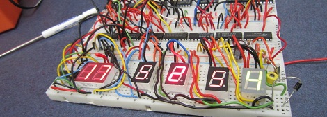
If you’re going to learn digital logic, why not aim high? That’s what [Easton] and his friend did when they built a clock using only 4000-series logic chips. On a breadboard, no less.

For a 1 Hz clock, [Easton] and his friend used a 4060 counter paired with a flip flop. This counts off 59 seconds until, with the help of an AND gate, the seconds counter rolls over to zero. After repeating that again for the minutes and building a similar circuit for the hour, and [Easton] had a working 4000-series 24-hour clock.

The breadboard clock may not be the prettiest thing, or a textbook example of how to prototype circuits,  but that was fixed with [Easton]’s friend’s PCB layout of a 12-hour clock. We couldn’t find any pics of this, but we’re sure it’s awesome and a great way to learn about logic and design.

Record Sound Without A Microcontroller

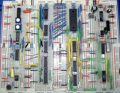
For his A-level electronic course work, [Andrew] decided to build a digital sound recorder that doesn’t use a microcontroller.

[Andrew]’s build captures audio from an on board microphone at 8000 samples/second. The audio is digitized into 8-bit sound data and sent to an SRAM. The recording and playback functions are controlled entirely by 4000-series logic chips. He admits the sound quality is pretty poor; this is mostly due to the 8kHz sample rate. In some circles, though, a terrible sample rate is seen as being pretty cool so we’re not going to say [Andrew]’s build is useless.

There’s some pretty smart design choices in [Andrew]’s build, like a cut off filter on the microphone set at 4000 Hz (the Nyquist frequency of his system).  For the recording medium, he used an SRAM that can hold about half a megabyte of data. At 8000 samples/second,  [Andrew]’s build can store a little more than 60 seconds of audio. The build may not be a logic chip computer, but there’s not any question in our mind that [Andrew] learned something. Check out [Andrew]’s 66-page coursework report here (PDF warning).

Working With VFDs

vfd

We love old display technology, like Nixie tubes, but they’re often difficult to work with because they require higher voltages than digital logic. Vacuum florescent displays (VFD) fall into this category. While not necessarily “old”, they are becoming far less common than LCDs. The main benefit of a VFD is that it actually produces light directly; it doesn’t require a backlight. You’ll find these displays on various players and appliances: CD, DVD, VCR, microwaves, stoves, car headunits, and others.

[Sprite_tm] had written off some VFDs, but recently revisited them with renewed interest. He started by testing what sort of voltage would be required to drive the display. It took 3V for the filament plus 15V to drive the grids. There are VFD controller chips available, but he wanted to get this working with what he had on hand. He had experience with older 40xx series logic, which can be powered by much higher voltages than 5V 74xx. His final schematic has three 4094 serial to parallel chips with an ATtiny2313 controller. A 5V power supply is dropped to 3V with diodes to drive the filament while a boost converter brings it up to 15V for the 4094s that switch the segments. While the code is specific to this display, it would be a great place to start your own project.