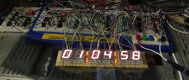
Inside The Clapper

clapper

Hackaday readers above a certain age will probably remember the fabulously faddish products developed by Joseph Enterprises. These odd gadgets included the Ove’ Glove, VCR Co-Pilot, the Creosote Sweeping Log, and Chia Pet (Cha-Cha-Cha-Chia) as mainstays of late night commercials, but none were as popular as The Clapper, everyone’s favorite sound-activated switch from the 1980s. [Richard] put up a great virtual teardown of The Clapper, that provides a lot of insight into how this magic relay box actually works, along with some historical context for the world The Clapper was introduced to.

Sound activated switches are nothing new, but the way The Clapper did it was just slightly brilliant. Instead of listening to every sound, the mic inside the magic box sends everything through a series of filters to come up with a very narrow bandpass filter centered around 2500 Hz. This trigger is analyzed by a SGS Thompson ST6210 microcontroller ( 4MHz, ~1kB ROM, 64 bytes of RAM, and 12 I/O pins ) to listen for two repeating triggers  within 200 milliseconds. The entire system – including the source code for the MCU – can be seen in the official patent, US5493618.

The Clapper sold many millions of units at a time when a lot of homes were assuredly in a pre-microelectronics world. Yes, in 1986, a lot of TVs had microcontrollers and maybe a washer/dryer combo may have had a few thousand transistors between them. Other than that, The Clapper was many household’s introduction to the ubiquitous computing power we see today, and all with less capability than an Arduino.

Homebuilt 30kV High Voltage Power Supply

If you have need for 30,000 volts to launch your ionocraft (lifter) or power other DIY projects then shuttle over to RimstarOrg’s YouTube channel and checkout [Steven Dufresne’s] homebuilt 30kV power supply. The construction details that [Steven] includes in his videos are always amazing, especially for visual learners. If you prefer text over video he was kind enough to share a schematic and full write up at rimstar.org.

The power supply can be configured for 1.2kV – 4.6kV or 4kV – 30kV at the output while requiring 0-24V DC at the input. In the video [Steven] tries two power supplies. His homemade DC bench power supply at 8V and 2.5A and also a laptop power supply rated at 20V 1.8A DC. A couple of common 2N3055 power transistors, proper wattage resistors, a flyback transformer and a high voltage tripler is about all you’ll need to scrounge up. The flyback transformer can be found in old CRT type televisions, and he does go into details on rewinding the primary for this build. The high voltage tripler [Steven] references might be a bit harder to source. He lists a few alternates for the tripler but even those are scarce: NTE 521, Siemens 76-1 N094, 1895-641-045. There are lots of voltage multiplier details in the wild, but keep in mind this tripler needs to operate up to 30kV.

Join us after the break to watch the video and for a little advice from Mr. Safety.

Continue reading “Homebuilt 30kV High Voltage Power Supply”

What’s Inside A 555?

555

The 555 timer chip is a ubiquitous piece of technology that is oft-considered the hardcore way of doing things. Of course, the old timers out there will remind us that discrete transistors are the badass way of doing things, and tubes even more so. It’s not quite at the level of triodes and transformers, but Evil Mad Scientist’s discrete 555 kit is still an amazing piece of kit.

Instead of transistors and resistors etched into silicon as in the OG 555, [Windell] over at EMS turned the basic circuit inside a 555 into a mega-sized version using discrete components. Your parts bins need new scale if you’re going to work with this and other up-scaled hobby electronic components.

Although the integrated stand that makes the whole package look like an overgrown DIP doesn’t break out the signals on the board, it does include some neat screw terminals for alligator clips and bits of wire so this kit can be used in a circuit. Because it uses discrete components, you can also take a meter or scope to check out how a 555 chip works from the inside.

The Easy Or Hard Way To Build A PWM Dimmer

From what you would gather from Hackaday’s immense library of builds and projects over several years, the only way to do PWM is with a microcontroller, some code, a full-blown IDE, or even a real-time operating system. To some readers, we’re sure, this comes naturally and with an awesome toolchain it can be as easy as screwing in a light bulb. There is, of course, an easier way.

[Jestin] needed to vary the current on a small 12 Volt load. Instead of digging out an in system programmer, he turned to the classic 555 chip. With a single pot, it’s easy to vary the duty cycle of the 555 and connect that to a MOSFET. Put a load in there, and you have a very easy circuit that’s a fully functioning PWM dimmer.

If all you have are a few scraps in your part drawers, this is a very, very easy way to set up a dimmer switch. We’re also loving [Jestin]’s improv aluminum tube enclosure, as seen in the video below.

Continue reading “The Easy Or Hard Way To Build A PWM Dimmer”

The Nibbler: A 4-bit CPU Built With 7400 Logic

nibbler-schematic

Maybe we shouldn’t say “built” since [Steve Chamberlin] hasn’t actually heated up his iron yet. From the finished schematic above that is puzzling at first, until you realize the scope of the project. His Nibbler implements a 4-bit CPU using 7400 logic chips. Because he’s come up with the architecture himself he’s taking a lot of steps to check all of his work before committing to a PCB.

We linked to his category for the project which is still in progress. Most recently he wrote a program to prove that it’ll run on the hardware. That’s a feat considering this is still just a design idea. It was made possible because he wrote a simulator based on the design. The C++ tool simulates data and control buses and features a full set of debugging tools.

Careful testing of the design before the build is the best possible way to go. The simulator and debugging tools will be useful for software development even after the hardware is built. And testing before wiring is a must as these things get out of control quickly in terms of soldering complexity.

[via Dangerous Prototypes]

Making Asteroids Miniature

Asteroids

Mini arcade cabinet builds are fairly common, but we’ve never seen anything like [Jurgen]’s mini vector Asteroids cabinet that takes an original Asteroids circuit board and a true vector monitor and shrinks it down to table top size.

Unlike the raster monitors of a later generation’s arcade games, the original Asteroids cabinet used a vector monitor just like one would find in an oscilloscope. [Jurgen] found the perfect CRT in, of all places, a broken Vectrex console. The video circuitry in the Vectrex was rather primitive and the beam deflection was far too slow for the video signals generated by the Asteroids PCB. To get around this, [Jurgen] added a custom XY driver board. While the Asteroids game – and other vector Atari games – were designed for a screen with 1 MHz of bandwidth, [Jurgen] found that 300 kHz was ‘good enough’ to display proper Asteroids graphics.

While the cabinet isn’t a miniaturized version of any proper cabinet, [Jurgen] did manage to build a rather nice looking case for his luggable version of Asteroids. The exposed PCB on the back is a great touch, and an awesome project for any ancient video game aficionado.

[Ken Shirriff] Completely Reverse Engineers The 1974 Sinclair Scientific Calculator

Wow. Seriously… Wow! The work [Ken Shirriff] put into reverse engineering the Sinclair Scientific is just amazing. He covers so much; the market forces that led [Clive Sinclair] to design the device with an under-powered chip, how the code actually fits in a minuscule amount of space, and an in-depth look at the silicon itself. Stop what you’re doing and read it right now!

This calculator shoe-horned itself into the market when the HP-35 was king at a sticker price of $395 (around $1800 in today’s money). The goal was to undercut them, a target that was reached with a $120 launch price. They managed this by using a Texas Instruments chip that had only three storage registers, paired with a ROM totaling 320 words. The calculator worked, but it was slow and inaccurate. Want to see how inaccurate? Included in the write-up is a browser-based simulator built from the reverse engineering work. Give it a try and let us know what you think.

Now [Ken] didn’t do all this work on his own. Scroll down to the bottom of his post to see the long list of contributors that helped bring this fantastic piece together. Thanks everyone!

[Thanks Ed]