Sometimes you just know that you have the best ever idea for a hardware product, to the point that you’re willing to quit your job and make said product a reality. If only you can get the product and its brilliance to people, it would really brighten up their lives. This was the starry-eyed vision that [Simon Berens] started out with in January of 2025, when he set up a Kickstarter campaign for the World’s Brightest Lamp.
At 50,000 lumens this LED-based lamp would indeed bring the Sun into one’s home, and crowdfunding money poured in, leaving [Simon] scrambling to get the first five-hundred units manufactured. Since it was ‘just a lamp’, how hard could it possibly be? As it turns out, ‘design for manufacturing’ isn’t just a catchy phrase, but the harsh reality of where countless well-intended designs go to die.
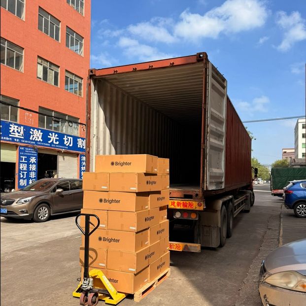
The first scramble was to raise the lumens output from the prototype’s 39K to a slight overshot at 60K, after which a Chinese manufacturer was handed the design files. This manufacturer had to create among other things the die casting molds for the heatsinks before production could even commence. Along with the horror show of massive US import taxes suddenly appearing in April, [Simon] noticed during his visit to the Chinese factory that due to miscommunication the heatsink was completely wrong.
Months of communication and repeated trips to the factory follow after this, but then the first units ship out, only for users to start reporting issues with the control knobs ‘scraping’. This was due to an issue with tolerances not being marked in the CNC drawings. Fortunately the factory was able to rework this issue within a few days, only for users to then report issues with the internal cable length, also due to this not having been specified explicitly.
All of these issues are very common in manufacturing, and as [Simon] learned the hard way, it’s crucial to do as much planning and communication with the manufacturer and suppliers beforehand. It’s also crucial to specify every single part of the design, down to the last millimeter of length, thickness, diameter, tolerance and powder coating layers, along with colors, materials, etc. ad nauseam. It’s hard to add too many details to design files, but very easy to specify too little.
Ultimately a lot of things did go right for [Simon], making it a successful crowdfunding campaign, but there were absolutely many things that could have saved him a lot of time, effort, lost sleep, and general stress.
Thanks to [Nevyn] for the tip.