Regular Hackaday readers will no doubt be familiar with the work of Matthew Alt, AKA [wrongbaud]. His deep-dive blog posts break down hardware hacking and reverse engineering concepts in an engaging way, with practical examples that make even the most complex of topics approachable.
 But one of the problems with having a back catalog of written articles is making sure they remain accessible as time goes on. (Ask us how we know.) Without some “algorithm” at play that’s going to kick out the appropriate article when it sees you’re interested in sniffing SPI, there needs to be a way to filter through the posts and find what’s relevant. Which is why the new “Roadmap” feature that [wrongbaud] has implemented on his site is so handy.
At the top of the page you’ll find [wrongbaud]’s recommended path for new players: it starts with getting your hardware and software together, and moves through working with protocols of varying complexity until it ends up at proper techno wizardry like fault injection.
Clicking any one of these milestones calls up the relevant articles — beginners can step through the whole process, while those with more experience can jump on wherever they feel comfortable. There’s also buttons that let you filter articles by topic, so for example you can pull up anything related to I2C or SPI.
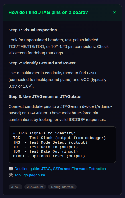
Further down the page, there’s a helpful “Common Questions” section that gives you a brief overview of how to accomplish various goals, such as identify an unknown UART baud rate, or extract the contents of an SPI flash chip.
Based on the number and quality of the articles, [wrongbaud]’s site has always been on our shortlist of must-see content for anyone looking to get started with hardware hacking, and we think this new interface is going to make it even more useful for beginners who appreciate a structured approach to learning.