I Can Fix The Space Station With A Metronome, A Metronome, A Metronome

ISS

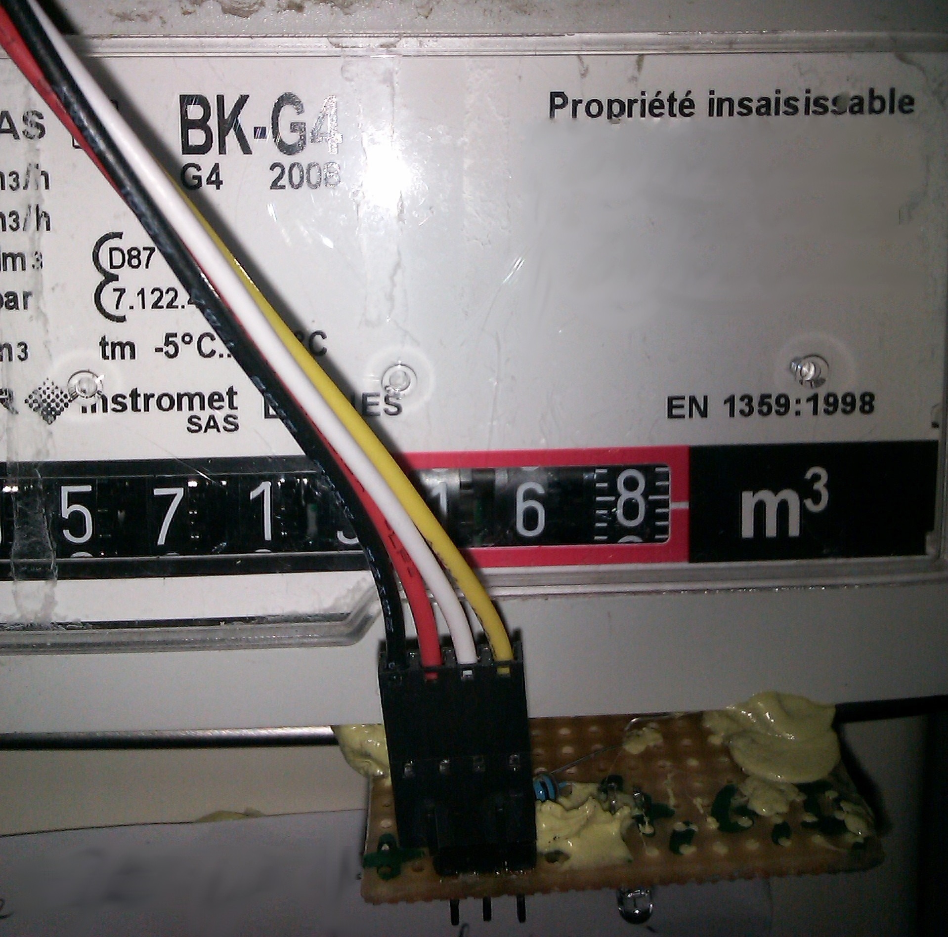
If the space station were left to its own devices, the living quarters would get incredibly hot. There are computers, hardware, and six crew members, all generating heat that must be gotten rid of. To do this, there are two heat exchangers inside the station that take warm water, dump that heat to ammonia, and send that ammonia out to panels outside the station. On December 11, 2013, Loop A of the thermal control system shut down, putting the station one failure away from evacuation. Plans for a spacewalk were tabled, but the ground crew managed to fix this hardware failure by telling the astronauts to push buttons, a metronome, and a software patch.

The problem with Loop A of the Internal Thermal Control System was a flow control valve that regulated the amount of ammonia flowing through the heat exchange. Too much ammonia, and the station would be far too cold. Too little, and it would be too hot. This valve is electronically controlled and takes exactly 13 seconds to move from open to closed. The first attempt at fixing the problem was having ground crew send the command to open the valve and cut the power halfway through. This involved using a metronome app on a phone to send two commands 6.5 seconds apart. It worked, but not quite well enough.

The failure of the metronome technique led [Todd Quasny] to write a script to turn the ‘on’ and ‘off’ commands from the ground to the ISS with millisecond resolution. This meant the commands to control the valve could be sent with the right delay, but they weren’t received with the right delay. This is a problem that had to be fixed from the station’s computers.

To finally solve the problem, ISS software engineer [Steve Joiner] was called in to write a software patch for the thermal control system. This is spaceflight and writing software is a long a laborious process of testing and code reviews. Nevertheless, the team managed to write and upload a patch in just two days.

This patch gave controllers the ability to control the valve with a resolution of 100 milliseconds, good enough for very fine control of the thermal system, and all without requiring the massive amount of planning that goes into a spacewalk or resupply mission.

Ups to [Ed Van Cise] for this tip. If you’re curious about the headline….

The Mystery Of Zombie RAM

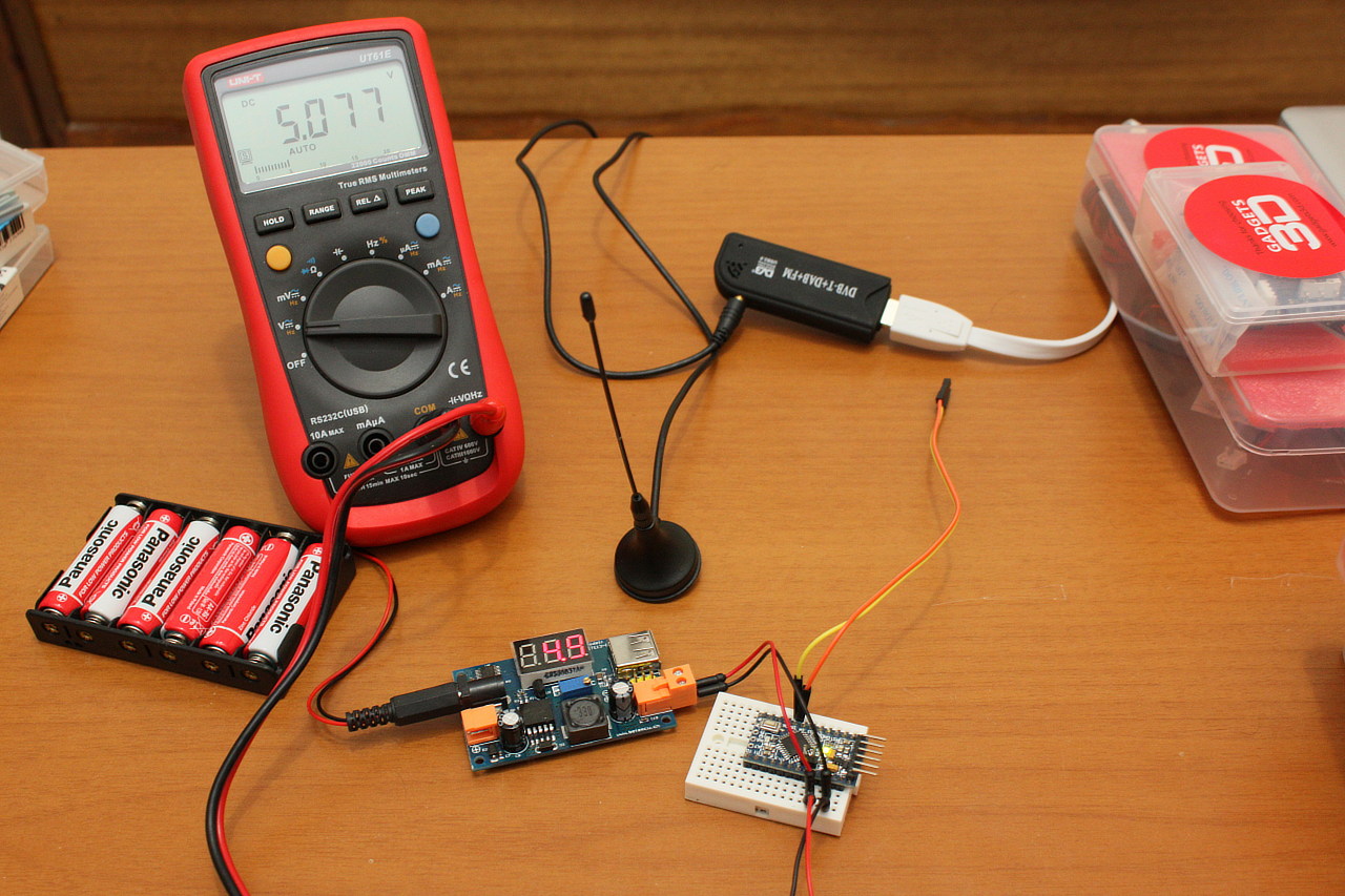
[Josh] had a little project where he needed to keep a variable in RAM while a microcontroller was disconnected from a power source. Yes, the EEPROM on board would be able to store a variable without power, but that means writing to the EEPROM a lot, killing the lifetime of the chip. He found an ATTiny can keep the RAM alive for a variable amount of time – somewhere between 150ms and 10 minutes. Wanting to understand this variability, he decided to solve the mystery of the zombie RAM.

The first experiment involved writing a little bit of code for an ATTiny4313 that looked for a value in RAM on power up and light up a LED if it saw the right value. The test circuit consisted of a simple switch connected to the power pin. Initial tests were astonishing; the ATTiny could hold a value in RAM for up to 10 minutes without power.

With the experiment a success, [Josh] updated his project to use this new EEPROM-saving technique. Only this time, it didn’t work. The value hidden away in RAM would die in a matter of milliseconds, not minutes. After tearing his hair out looking for something different, [Josh] rigged up an Arduino based test circuit with humidity and temperature sensors to see if that had any effect. It didn’t, and the zombie RAM was still not-undead.

The key insight into how the RAM in an ATtiny could stay alive for so long came when [Josh] noticed his test circuit had a LED, but the actual project didn’t. Apparently this LED was functioning as a very tiny solar cell, generating a tiny bit of current that kept the RAM alive. A dark room with a flashlight confirmed this hypothesis, and once [Josh] gets his uCurrent from Kickstarter he’ll know exactly how much current this LED is supplying.

Turning A Tiny CRT Into A Monitor

TV

[GK] picked up a few tiny 2″ CRTs a while back and for the longest time they’ve been sitting in a box somewhere in the lab. The itch to build something with these old tubes has finally been scratched, with a beautiful circuit with Manhattan style construction.

[GK] has a bit of a fetish for old oscilloscopes, and since he’s using an old ‘scope tube, the design was rather simple for him; there aren’t any schematics here, just what he could put together off the top of his head.

Still, some of [GK]’s earlier projects helped him along the way in turning this CRT into a monitor. The high voltage came from a variable output PSU he had originally designed for photomultiplier tubes. Since this is a monochrome display, the chrominance was discarded with an old Sony Y/C module found in a part drawer.

It’s a great piece of work that, in the words of someone we highly respect is, “worth more than a gazillion lame Hackaday posts where someone connected an Arduino to something, or left a breadboard in a supposedly “finished” project.” Love ya, [Mike].


The Credit Card Sized GameBoy

Think you’ve seen every possible type of Arduino based hand held video game? [Kevin] managed to coax something new out of the theme with a very clever credit card sized console that uses some very interesting construction techniques.

The inspiration for this project began when [Kevin] dropped an SMD resistor into a drill hole on a PCB. This resistor fell right through the hole, giving him the idea creating a PCB with milled cutouts made to fit SMD components. With a little experimentation, [Kevin] found he could fit a TQFP32 ATMega328p  – the same microcontroller in the Arduino – in a custom square cutout. The rest of the components including a CR2016 battery and OLED display use the same trick.

The rest of the design involved taking Adafruit and Sparkfun breakout boards, and modifying the individual circuits until something broke. Then, off to Eagle to create a PCB.

[Kevin]’s experiment in extremely unusual PCB design worked, resulting in a credit-card sized “Game Boy” that’s only 1.6 millimeters thick. The controls are capacitive touch sensors and he already has an easter egg hidden in the code; enter the Konami code and the Hackaday logo pops up to the tune of [Rick Astley]’s magnum opus.

Now [Kevin] is in a bit of a bind. He’d like to take this prototype and turn it into a crowd sourced campaign. In our opinion, this “Game Boy in a wallet” would probably do well on a site like Tindie, but any sort of large scale manufacturing is going to be a rather large pain. If you have any wishes, advice, of complaints for [Kevin] he’s got a few links at the bottom of his project page.

Breadboardable WS2812 LEDs

LED

Hackaday sees a ton of projects featuring the WS2812 series of digitally controllable RGB LEDs, in the form of bare chips, RGB LED strips, or some form of Adafruit’s NeoPixels. All these WS2812 LED products have one thing in common – they’re chip LEDs, making some projects difficult to realize. Now there’s a new member of the WS2812 family – a through-hole LED version – that should be available through the usual sources sometime later this year.

The key difference between these and the usual WS2812 LEDs is the packaging; these are 8mm LEDs with pins for power, ground, data in, and data out. With the preexisting libraries, this 8mm LED should work just the same as any other WS2812 LED.

Aside from a through-hole package, these new LEDs are very diffuse and aren’t as blinding as the normal chip LEDs. If you want to pick up a few of these LEDs, they’re available here, 13 LEDs for $15. There’s a lot of potential here for RGB LED cubes, something we hope to see sooner rather than later.

Hackaday 68k: A New Hackaday Project

It’s no secret Hackaday loves retrocomputers, classic hardware, and vintage tech. Now that we have a great way to present long-form projects, it only makes sense that we combine our loves with a new build. Over the next few months, I’ll be developing a homebrew computer based on the Motorola 68000 CPU, documenting everything along the way, and building a very capable piece of hardware that will end up hosting a few Hackaday webpages. I already have a solid start on the project and will be posting on our front page to discuss the major parts already in progress, and those yet to come.

There are a few reasons we’re taking on this project. With few exceptions, most of the homebrew projects we see are based around 8-bit micros – specifically the 6502 and Z80. 16 and 32-bit CPUs really aren’t that much more difficult to work with, and if we can spearhead a renaissance of the 68k, 65816, or even a 386 (!), we’re all for that. Also, it’s been suggested that we host the Hackaday Retro site on retro hardware, and what better way to do that by documenting a build on our new project hosting site?

That’s a very brief introduction to this project. Let’s take a closer look at what hardware we’ll be using, what software we’ll get running, and what you can do to help.

Continue reading “Hackaday 68k: A New Hackaday Project”

FT232RL: Real Or Fake?

Above are two FTDI FT232RL chips, an extremely common chip used to add a USB serial port to projects, builds, and products. The one on the left is a genuine part, while the chip on the right was purchased from a shady supplier and won’t work with the current FTDI drivers. Can you tell the difference?

[Zeptobars], the folks behind those great die shots of various ICs took a look at both versions of the FT232 and the differences are staggering. Compared to the real chip, the fake chip has two types of SRAM etched in the silicon – evidence this chip was pieced together from different layouts.

The conclusion [Zeptobars] reached indicated the fake chip is really just a microcontroller made protocol compatable with the addition of a mask ROM. If you’re wondering if the FTDI chips in your part drawers are genuine, the real chips have laser engraved markings, while the clone markings are usually printed.