A Microwave Frequency Doubler

It is an age-old problem. You have a 2.5 GHz source and you want it at 5 GHz. You need a frequency doubler. [All Electronics Channel] has an interesting video that talks not only about the theory of such a device but shows a practical one made with copper strips on a blank PCB substrate.

A fun thing about microwaves is that even little strips of copper are circuit elements since the wavelength at 2.5 GHz is only 12cm. That means a quarter-wave stub is only 3 cm — just over an inch.

The construction technique used is simple and, as he points out, experimenting with a real circuit will give you much more feel for how these circuits work than just reading and working out the math.

The multiplier drives an amplifier into nonlinearity which, of course, generates harmonics. Then a bandpass filter selects the second harmonic. If you haven’t dealt with stub circuits before, you might want to read up on how a piece of copper connected at one end can act like an inductor, a capacitor, or even a tuned circuit.

If you want more detail on the copper tape technique, we can help. If you don’t want to double frequency, maybe you would prefer to try voltage.

Continue reading “A Microwave Frequency Doubler”

The Simplest Way To Spot 2.4GHz RF

When the cool kids are showing off their SDRs it’s easy to forget that a radio receiver can be very simple indeed. The crystal set is one of the earliest forms of radio receiver, a tuned circuit and a diode that would pick up those AM broadcast stations no problem. But lest you imagine that these receivers can only pick up those low frequencies, here’s Hackaday alum [Ted Yapo] with a handy 2.4GHz receiver that picks up strong WiFi and microwave oven leakage.

It’s about as simple as it gets, an LED with a UHF diode in reverse across it. The clever part lies in the wire leads, which are cut to resonate as a dipole at 2.4 GHz. The resulting RF voltage is rectified by the UHF diode, leaving enough DC for the LED to flash. If you are wondering why the LED alone couldn’t do the job as a rectifier you would of course be on to something, however its much worse high frequency performance would make it not up to the job at this frequency.

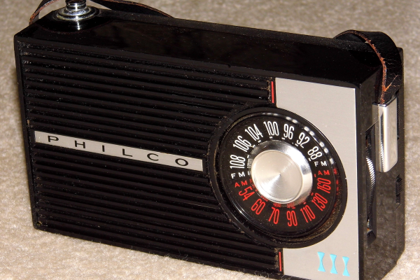
The glory days of analogue broadcasting may now be in the past, but it’s still possible to have fun with a more conventional crystal radio. If you are adventurous, you can even make one that works for the FM, band too.

Front view of vintage radio, with small screen inset into tuner.

Vintage Radio Gets Internet Upgrade

There’s nothing quite like vintage hardware, and the way it looks and works is something that can be worth celebrating. [Old Tech. New Spec] did that with his loving modification of a 1964 Dansette portable radio, bringing it into the modern era by giving it the ability to play Internet radio stations while keeping all the original controls and appearance. As he says, you’d hardly know it has been modified unless you turned it on.

Internet radio station logos scrolling across small LCD screen
A full color LCD behind a convex lens matches the radio’s aesthetic.

A real centerpiece of this conversion is that the inner part of the tuning dial has been replaced with a full color LCD display that shows, among other things, the logo of whatever Internet radio station is currently playing. The combination of LCD and convex lens looks fantastic, and blends beautifully into the aesthetic.

Inside the device is a Raspberry Pi, some simple Python scripts, and a Pirate Audio board. Together, they handle the job of audio streaming and output, displaying album art, and accepting inputs for playback controls. A large power bank ensures the result remains portable, and as usual with vintage hardware, there’s no worry about fitting everything inside. Watch it in action in the video embedded below. (And if the name of the audio board got you excited, but you’re disappointed to discover there’s no actual pirate broadcasting happening? Well, the Raspberry Pi can do that, too.)

Continue reading “Vintage Radio Gets Internet Upgrade”

Arduino Becomes Superhet With A Little Help From Friends

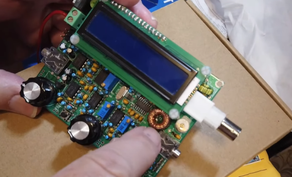
A radio receiver is always a fun project. [Jayakody2000lk] decided that his new superheterodyne design would use an Arduino and it looks like it came out very nicely. The system has four boards. An off-the-shelf Arduino, a Si5351 clock generator board (also off-the-shelf), and two custom boards that contain the IF amplifier and mixer.

The receiver started out in 2015 without the Arduino, and there’s a link in the post to that original design. Using the Si5351 and the Arduino replaces the original local oscillator and there have been other improvements, as well. You can see a video about the receiver below.

Tuning is by a rotary encoder and the current software lets you tune from about 4.75 MHz to a little over 15.8 MHz. Of course, you could change to any frequency the Si5351 can handle as long as the mixer and other components can handle it. The IF frequency is the usual 455 kHz.

If you decide to build this yourself, the design files are on GitHub. Overall a very nice and neat design. We are always amazed how little radio architecture has changed since Edwin Armstrong’s day. Of course, we have better components, even if they aren’t meant for radio purposes.

Continue reading “Arduino Becomes Superhet With A Little Help From Friends”

Shortwave Radio Picks Up Sideband

With the push to having most of a radio receiver as part of a PC, it might seem odd to have a standalone communication receiver, but [OM0ET] reviews the latest one he picked up, an ATS25. Inside isn’t much: a battery, a speaker, an encoder, and a Si4732 that provides the RF muscle.

It appears the receiver is pretty broadband which could be a problem. [OM0ET] suggests adding selectivity in the antenna or adding an extra board to use as a bandpass filter.

Continue reading “Shortwave Radio Picks Up Sideband”

A Bird 43 wattmeter and its homebrew equivalent

Homebrew Wattmeter Pays Homage To Sturdy Original

If there’s one instrument that hams and other radio enthusiasts covet, it’s the venerable Bird 43 Thruline wattmeter. The useful RF tool has barely changed in the nearly 70 years since it was first introduced, and they’re built like a tank. This makes Bird meters highly desirable, and therefore quite expensive either brand new or on the swap-meet circuit.

But radio amateurs are nothing if not resourceful, and building a homebrew version of the Bird wattmeter (in Portuguese; Google translate tool at the bottom of the page) as Brazilian ham [Luciano Sturaro (PY2BBS)] did is a good way to get your hands on one. Granted, [Luciano] had a head start: a spare line set, which is the important bit from a Bird wattmeter. The machined metal part is in effect an air-insulated section of coaxial cable that the RF signal passes through on its way from transmitter to antenna. A “slug” is inserted into the cavity in the line set to sense the RF and couple it to the meter electronics; the slug can be rotated to measure RF traveling in either direction, allowing the user to determine how much RF is getting reflected by the antenna system.

[Luciano]’s version of the meter is faithful to the sturdy construction of the original, with a solid steel case that mimics its classic lines — the case even sports the same color scheme and stout leather carry handle. There are some changes to the electronics, and the meter movement itself is different from the original, but all in all, the “Buzz 50” looks fantastic. We especially love the detailed nameplate as an homage to Bird.

The thing about Bird — and Bird-like — meters is that the slugs are like potato chips; you can’t have just one. Curious as to how these slugs work? Check out this slug repair project.

[Featured image of Bird 43 Wattmeter: Martin RF Supply]

Thanks to [Niko Huenk] for the tip!

The Simplest FT8 Transceiver You’ll Ever Build

Probably the most interesting facets of amateur radio in 2021 lie in the realm of digital modes. Using the limitless possibilities of software defined radios has freed digital radio communication from the limits of what could be done with analogue electronics alone, and as a result this is a rare field in which radio amateurs can still be ahead of the technological curve. On of these newer digital modes is FT8 created by the prolific [Joe Taylor K1JT].

And it’s for this  mode that [Charles Hill] has created an easy-to-build transceiver. Its brains are aTeensy 3.6, while the receive side is a Si4735 receiver chip and the transmitter is a Si5351 programmable clock chip driving a Mini-Circuits GVA84 power amplifier with an appropriate filter. The interface is via a touchscreen display. It relies on existing work that applies a patch on-the-fly to the Si4735 receiver chip for SSB reception, and another project for the FT8 software.

The charm of this transceiver is that it can be assembled almost in its entirety from modules. Some radio amateurs might complain that homebrew radios should only use the most basic of components assembled from first principles, but the obvious answer to that should be that anything which makes radio construction easier is to be welcomed. If the 100 mW output power seems a bit low it’s worth remembering that FT8 is a weak signal mode, and given the right propagation conditions the world should be able to hear it despite the meagre output.

We’ve featured quite a few radios using the Si47XX series, which can be made into very tidy receivers indeed.