LED Backlight Conversion Using Recycled CCFL Inverter Parts

inverter_repair

[Ammon] repairs busted LCD monitors as a side hobby, so replacing burned out CCFLs and inverter circuits is something he can do in his sleep. One Dell monitor he received had him so perplexed, that he simply gave up on trying to repair the inverter circuit. He still wanted to get it working, so he had some narrow PCBs made and started working on his LED replacement backlight.

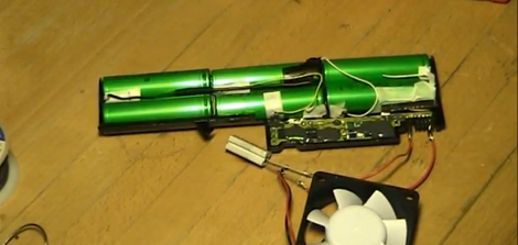
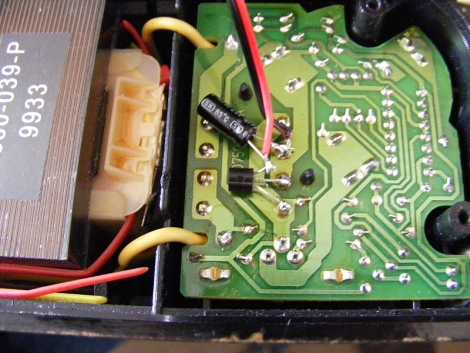
He built a driver board for the LEDs, populated with left over components that he stripped from the LCD panel’s inverter circuit. He needed space to insert his driver board, so he simply cut out a chunk of the inverter board and slipped his replacement driver board in its place. As you can see in the picture above, his board (in green) takes up far less space than the original inverter circuit it replaces.

He provides a schematic for his circuit as well as a PCB layout file, so it should be fairly easy to replicate his work. He has not posted schematics or layout information for his LED strips, but we’re betting he will if someone asks nicely.

Check out this pair of posts if you are interested in reading more about replacing your burned out CCFL with LEDs.

Heat Gun GPU Reflow Fixes Laptop

Solder connections on processors seem to be a very common failure point in modern electronics. Consider the Red Ring of Death (RRoD) on Xbox 360 or the Yellow Light of Death (YLoD) on PlayStation 3. This time around the problem is a malfunctioning Nvidia GPU on an HP Pavilion TX2000 laptop. The video is sometimes a jumbled mess and other times there’s no video at all. If the hardware is older, and the alternative to fixing it is to throw it away, you should try to reflow the solder connections on the chip.

This method uses a heat gun, which we’ve seen repair PCBs in the past. The goal here is to be much less destructive and that’s why the first step is to test out how well your heat gun will melt the solder. Place a chunk of solder on a penny, hold the heat gun one inch above it and record how long it takes the solder to flow. Once you have the timing right, mask off the motherboard (already removed from the case) so that just the chip in question is accessible. Reflow with the same spacing and timing as you did during the penny test. Hopefully once things cool down you’ll have a working laptop or gaming console again.

Repair Stuck IPod Nano Buttons

A system is only as strong as its weakest link and [Roberto Barrios] found that on the sixth generation iPod nano the buttons are the problem. It makes sense that the buttons would be exposed to wear since they’re movable parts. The issue isn’t one of contacts or springs wearing out, but how the buttons are assembled. Each consist of a couple of parts; the tactile piece that you see and press, the electrical switch which converts that force into an electrical signal, and a shim that bridges the gap between the two.

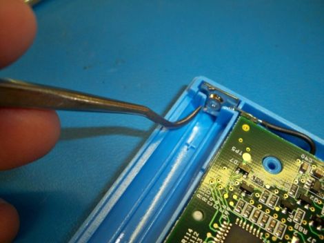
After two months of use the iPod [Roberto] was fixing had stopped responding to presses of the Power button. It turns out that the shims are attached with double-sided tape. Inspection of the internals revealed that the shim had slid to one side and no longer made contact with the electrical system. His solution was to remove the tape and clean off the goo, then reattach the shims using “two-part metal cement”.

With the shim back in place all is well but he made sure to execute this fix on all of the buttons before reassembly.

Switched Mode Power Supply Repair Guide

switched_mode_power_supply_repaiir

[Erich] spotted a broken DVD recorder at a local amateur radio meeting and decided to see if he could restore it to working order. While he was fortunate enough that someone labeled it as having a bad power supply, things aren’t always that easy. He gives a broad explanation as to how switched mode power supplies work as well as discusses some of the reasons these devices tend to fail. He identifies a few common components and areas that one should check while diagnosing a non-functioning power supply. While obvious bulging capacitors are easily identifiable, he discusses the need for an ESR meter and uses a kit-built model to test capacitors that do not have any visual signs of damage. While some of his walkthrough might be basic knowledge for readers who have experience in recapping circuit boards, it serves as a nice guide for those who are new to the world of electronics troubleshooting and repair.

Revive Your Tired Dremel Battery Pack

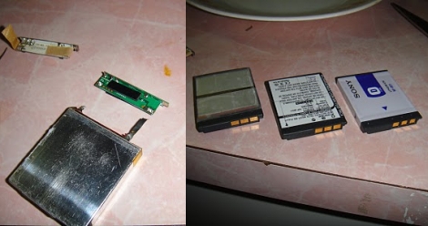
It turns out there’s nothing more than six Nickel Cadmium AA rechargeable batteries inside of that cordless Dremel battery pack. Yep, standard rechargeable AA’s that you can buy most anywhere, and now you can revive that aging battery pack by following [Stuuf’s] guide. Since you’re already at it, a few more bucks will yield a real upgrade by using the superior Nickel Metal Hydride batteries which should yield around three times as much use between charging. We totally understand having a battery pack, since the shape of the case is part of the handheld tool, and it should be easy to interchange the battery as one unit. We just wish that the battery pack had been designed to have the AA cells swapped out by the user once they had reached the end of the line.

Do you have other cordless tools in need of a pick-me-up? Check out this Makita battery pack repair hack for a point in the right direction.

[Thanks Bluewraith]

Reverse Engineering A PCB

Occasionally when a device breaks, the defect is obvious. Whether it is a blown fuse or a defective capacitor, generally the easy to see stuff is easy to fix. When a problem is more subtle, or when doing some more advanced tasks like adding functionality to a device, greater knowledge about a circuit board is required. While there might be details hidden in lower levels of PCB, often just knowing the mounted components and layout of the outside layers can be enough to create a rough schematic of a device. [Throbscottle] has put together an excellent guide for procedurally breaking down a photo of a board and turning it in to something useful. The guide utilizes some open source image processing software such as the GIMP, Inkscape, and Dia, all of which are widely available. Keep in mind this reverse engineering can be a time consuming process, but will almost definitely reward those patient enough to work through it.

[Thanks to everyone who sent this in!]

Fixing The Rovio Battery Charging Circuit

[Chris] was unhappy with the battery performance of his Rovio. It seems that he’s not alone, so he set out to reverse engineer the battery charging circuit to see if there was a fix. Boy is there, what he found is the diode above, apparently installed backwards when compared to the silk screen diode symbol. Now it’s entirely possible that the silk screen is wrong and this was fixed during assembly. We think that’s unlikely because if the closer of the two diodes was supposed to have the same polarity as the one next to it there should have been room to install them both in exactly the same orientation. [Chris] pulled out a soldering iron and changed the diode to match the silk screen. That fixed his problem and he’s now getting better performance than he ever has.

[From our comments section]