When you need to match paint colors, one of the tools you’ll reach for is a deck of reference colors. Another might be a colorimeter. But what if you want both? [hallko1234] created just that by reverse-engineering and then patching a CR4501 colorimeter.
It starts with a problem: every time [hallko1234] needed to check a color, he had to take a reading, write it down, run to the office, match it with a table, and then walk all the way back. That sounds like too much effort. The natural solution, of course, is to automate the process.
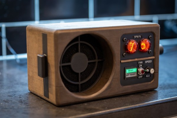
So he did. The CR4501 will happily give you its entire firmware over the debug port, after which it was time for analysis in Ghidra. Some hiccups, brickings and accidental erasure of calibration data later, he finally had a working version. The end result is a simple screen that, after every time you measure, displays the closest RAL color code and how close it is.
On the off chance someone else has the same colorimeter, he even made an online tool to install it for you.


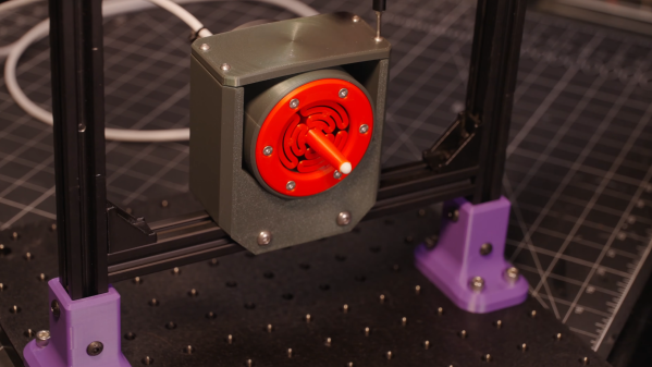
 Cutting foam with a hot wire is a common technique to shape foam in a wide variety of shapes. If you want to cut something detailed and precise, like an airfoil, you probably want to use a computer-controlled cutting tool. Here [Michael Rechtin] has been working on creating a very versatile DIY CNC hot wire cutter, with the results recently