Like a lot of us, [Andrea] has a habit of disassembling everything he runs into. He recently came across a fairly substantial motor he’d salvaged and envisioned its new life as a small circular saw.
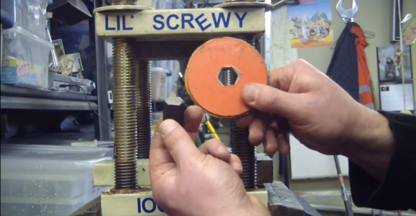
[Andrea] bought new cutting discs, but the rest is salvage and scrap. He had already mounted the motor, pivot, belt, and gear to a wood block, so he added two more wood scraps for a base and a cutting surface. He screwed a metal L beam to one side of the surface block to keep the disc adjacent to the edge. A couple of washers keep the disc rotating freely. [Andrea] used a piece of hydraulic pipe and a cylindrical nut to attach the disc to the pivot. This assembly can be easily tightened by hand, so changing discs is a quick operation.
He kept the electrical as-is and mounted the box to the saw body. This 30W motor runs at ~600-1000RPM which isn’t fast enough to cut wood. Undeterred, [Andrea] plans to use it to cut steel bolts, copper circuit boards, and metal plates. If you need to cut through anything and everything, try this 700W DIY table saw.