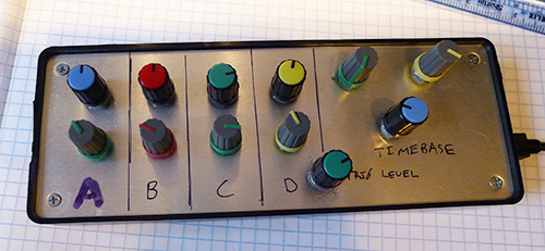
Forget Treating Your Diabetes – Use Your Insulin Syringe As A Logic Probe

syringe-logic-probe

Hackaday reader [JumperOne] was in need of a logic probe that he could use to reliably test some tiny .5mm pitch IC pins. The probe that came with his oscilloscope was a bit too big and not near sharp enough to do the job, but he figured that a syringe might do the trick nicely.

He drilled a small hole near the business end of the syringe, through which he fed a piece of stripped twisted pair cabling. [JumperOne] then soldered a pair of pins to a small piece of coaxial cable, attaching the opposite end to the twisted pair already in the syringe. After carefully coiling the thin cable around the needle, he secured the coaxial cable and its pins in place with a bit of hot glue.

[JumperOne] says that his makeshift logic probe works very well and the sharp needle would easily pierce through any oxidation or solder mask that stands in its way. One extra benefit of using a syringe as a probe is that they come complete with caps which help protect both ends of the delicate tool.

BGA Soldering With A Paint Stripper And Stopwatch

Having just received a shiny set of PCBs from the fab-house [Devbisme] needed a way to solder the main chip in place. It has a Ball-Grid Array footprint which is notoriously difficult to populate in a home lab. But he makes it look pretty easy and decided to share a video tutorial of the process.

The main tool he used is the paint stripper (heat gun) seen above. Since he didn’t have his own fancy reflow oven he made things work with the gun as his heat source. First he applies a generous layer of liquid solder flux to the BGA footprint on the board. Next he melts some solder onto the tip of his iron and uses it to tin all of the board’s BGA pads. Then it’s time for the critical step of positioning the chip. He uses vacuum tweezers to set it in place, and traditional tweezers to fine-tune its position. From here he heats with the paint stripper for two minutes, starting far above the board and slowly moving closer, with the reverse at the end of the soldering process. Once cool the board is cleaned with distilled water and blown dry with compressed air. After a visual inspection he finishes the application with a 30 minute stay in a 300 degree oven. We’ve included the video after the break for your convenience.

We’ve seen a similar technique used for replacing a chip on an already populated board.

Continue reading “BGA Soldering With A Paint Stripper And Stopwatch”

Turning A Webcam Into A Spectrometer

If you want to find out what something is made out of, you’ll probably be using a spectrometer. These devices allow scientists to determine what something is made of by shining light through an object and recording what colors are absorbed. Professional spectrometers cost many thousands of dollars, but you can build your own using a simple USB web cam, an old DVD-R, and a VHS cassette case.

In this tutorial of Public Labs’ DIY video spectrometer, [Jeffery] takes us through the process of building a spectrometer. After cutting a small bit of plastic from a DVD-R and mounting it on the lens of a web cam, [Jeff] puts the webcam in a VHS case and shines a light through a small slit. The result is a rainbow pattern captured by the webcam, and by putting different translucent materials in front of the light source, the spectrum slightly changes.

Of course a DIY spectrometer is nearly useless without a library of materials and their associated spectra. [Jeffery] is working on this as well with a wiki-style app called Spectral Workbench.

There’s a video tutorial for making your own DIY spectrometer available after the break. It seems like an easy build, if you can find the requisite VHS cassette case in your basement and/or attic.

Continue reading “Turning A Webcam Into A Spectrometer”

Making A Spray Booth From An Old Dishwasher

For several years, [Randy]’s spray paint booth was a simple cardboard box. Sure, it kept the overspray contained to a small area, but there was a lot of room for improvement. Luckily, after replacing his dishwasher he had the makings of an excellent spray paint booth that can be put together in a few hours.

The build began by tearing apart the old dishwasher and getting rid of just about everything; the door, plumbing, and electrical were all discarded leaving [Randy] with a plastic husk. After installing a small fluorescent light, plugging the drain hole, and making a simple lazy Suzan, [Randy] had a proper spray booth on his hands.

[Randy] opted not to put in a ventilation system; he was, after all, working with non-toxic vapors. If you’re planning on gutting a dishwasher for use with some nasty chemicals, it might be a good idea to use the drain hole as a ventilation port.

Prototyping With Very, Very Small ICs

Gone are the days when all the cool chips are able to be thrown into a breadboard very easily. [starlino] was working with a circuit that uses an accelerometer, but unfortunately these chips come in hard to solder LGA-16 packages. [starlino] figured out a way to prototype with these packages that doesn’t require a custom breakout board or spending any time watching a reflow oven.

[starlino]’s LGA-16 adapter board began with a piece of perf board drilled out to form a space that perfectly fits his accelerometer. A piece of tape is placed over the pads of the chip and perf board, and the gap between the chip and board is filled in with a two-part plumbers putty.

Once the putty has cured, the leads on the acclerometer are connected to the pads on the board with a silver conductive pen. After putting a few header pins in the corners of the board, [starlino] soldered the pads to the pins and had a permanent breakout board for a very small accelerometer.

It’s not by any means a pretty build, but after [starlino] sealed the entire build in liquid electrical tape and installed it in a DIP socket, he had a completely functional accelerometer in an easy to prototype package. Not bad for a breakout board that can be built from stuff just lying around a workbench.

Turning A 12 Year Old Mill Into A Modern Workhorse

Even though the Roland MDX-20 CNC mill fetched a pretty penny when it was first made available 12 years ago, there were a few features that made any builder lucky enough to own one scratch their head. The only way for a computer to communicate with this mill was through an RS-232 connection, and instead of a normal control protocol such as GCode, the Roland mill uses a very proprietary software package.

[Johan] fixed these problems and at the same time turned this wonderful machine into a tool for the 21st century. Now, instead of running a very long serial cable to his mill with a serial to USB converter at the end, he can just plug a USB cable into his mill with the addition of an FTDI USB to serial chip wired directly to the mill’s circuit board.

Stock, the Roland mill used a very strange proprietary communications protocol. [Johan] was able to reverse engineer this protocol by tracing out a few simple shapes and curves and taking a highlighter to the printout of the resulting file. Instead of the outdated software package that shipped with his mill, [Johan] can now export tool paths directly from his CAD program and send them over a USB cable.

It really is a shame such a nice machine like [Johan]’s mill suffered from the glaring shortsightedness of Roland executives 12 years ago, but at least now [Johan] has a machine that should easily last another decade.

Adding A Serial Trigger To A Logic Analyzer

If you’re attempting to debug a serial bus with a bare-bones logic analyzer, you’re going to have a bad time. Most of the inexpensive analyzers available don’t have a serial pattern trigger, or a way to start recording data after a specific pattern of bits comes down the pipe. [Neil] sent in a great little project that adds a serial trigger to these analyzers, we’ve got to hand it to him for designing such a useful board.

[Neil] designed a small board featuring a CLPD that converts serial data to parallel data. By setting the trigger condition of the logic analyzer to any 24-bit pattern he wants, it’s possible for [Neil] to sniff a serial bus exactly when he wants to.

The circuit is quite minimal, basically just a 100-pin CLPD and a bunch of 0.100″ header pins. It’s a useful tool, and although we couldn’t find the board file to make our own, we’re sure [Neil] will be providing that shortly.