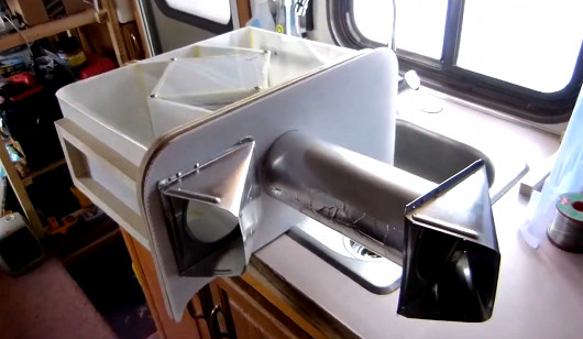
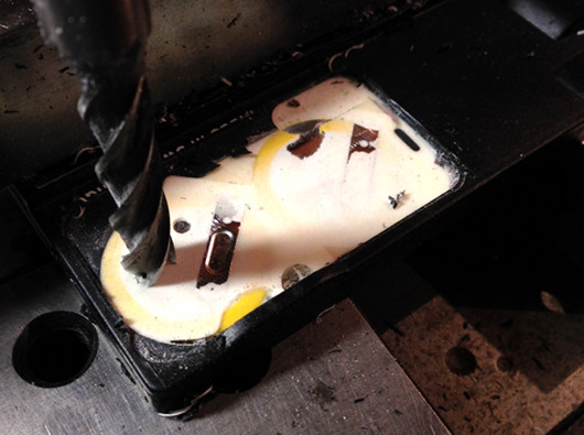
The Straddler Makes AVR Breadboarding Truly Plug And Play

the_straddler_avr_programmer

It’s not that breadboarding AVR circuits is difficult. But you have to admit that it takes some time to set everything up. We don’t label the top of our DIP chips so that you know what each pin does just by looking. Which means that wiring up the programmer involves pulling out the datasheet. [Vinnie] found the solution to this problem which is to make one of these interface PCBs for each AVR chip family. The long pins make it easy to drop over the top of your microcontroller, which is where the name comes from.

His first stab at the idea was just a hunk of home etched PCB which broke out the programming pins into the 6-pin ICSP standard. This second rendition uses the 10-pin standard and adds a few extras into the mix. He included decoupling capacitors which need to be used in every circuit anyway. There’s a crystal along with its load capacitors. This clock source is a snap to enable by burning some fuses. If you choose to use the internal oscillator instead this hardware won’t interfere. The LED is used to get you up and running with blinky firmware as quickly as possible. He plans to add jumper in the next revision which can disconnect this components from the I/O pin. Now you just need to add a 10-pin header to that USB keyboard AVR programmer and you’re in business.

Connecting An Old Scope To A Computer

Scope

A friend of [Michael]’s said his company was getting rid of some old lab equipment and asked him if he wanted a very large and very old digital storage oscilloscope. A ‘hell yes’ and we’re sure a few beers later, [Michael] found an old Gould 200 MHz four-channel scope on his bench. Even 20 years after its production it’s still a capable tool, but the serial ports on the back got [Michael] wondering – would it be possible to plot the screen of the scope on his computer?

The scope has three ports on the back – GPIB, miscellaneous I/O, and RS423. The latter of those ports is similar enough to RS232 that a USB to Serial converter just might work, and with the help of a null modem cable and a terminal, [Michael] was able to connect to this ancient scope.

In the manual, [Michael] found a the serial commands for this scope. The most useful of these is a command that prints out the contents of the scope’s trace memory as a series of 1-byte integers. With a short bit of PERL programming, [Michael] can create a PDF plot of whatever is on the scope’s screen. It’s formatted perfectly for Gnuplot, MATLAB, or even Excel.

Awesome work, and especially useful given these old scopes are slowly making their way to a technological boneyard somewhere.

Evalbot As A JTAG Programmer

evalbot-as-jtag-programmer

[Adarsh] needed a JTAG programmer to push code to a CPLD dev board he was working with. He knew he didn’t have a dedicated programmer but figured he could come up with something. Pictured above is his hack to use a Stellaris Evalbot as a programmer.

Long time readers will remember the Evalbot coupon code debacle of 2010. The kits were being offered with a $125 discount as part of a conference. We were tipped off about the code not know its restrictions, and the rest is history. We figure there’s a number of readers who have one collecting dust (except for people like [Adam] that used it as a webserver). Here’s your chance to pull it out again and have some fun.

A bit of soldering to test points on the board is all it takes. The connections are made on the J4 footprint which is an unpopulated ICDI header. On the software side [Adarsh] used OpenOCD with stock configuration and board files (specifics in his writeup) to connect to the white CPLD board using JTAG.

Upgrading A Fluke Multimeter With A Masterful Addition

LCD

The old Fluke 8050a multimeter from the 80s is an awesome piece of lab equipment. It’s built like a tank, and thanks to the newer more portable models, this old meter is available for a pittance on eBay. [Ken] picked up a few of these meters and decided to give one of them a little upgrade – a 2.2″ 320×240 LCD display that is a vast improvement on the old stock seven-segment numerical display.

Inside the Fluke 8050a is a 40-pin DIP processor that handles all the computations inside the unit. [Ken]’s solution to tap into this processor was to take a 40-pin PIC microcontroller, bend some of the pins backwards, and use the remaining pins to drive the new LCD display. It’s actually somewhat brilliant in its simplicity and looks really cool to boot.

The rest of the circuitry consists of a level converter and a few wires going directly to the LCD display. [Ken] already has another Fluke 8050a on the bench waiting for a facelift and some plans for a few improvements that include a bar graph, histogram, and possibly even a touch display.

Bode Plots On An Oscilloscope

bode

Bode plots – or frequency response graphs – are found in just about every piece of literature for high-end audio equipment. It’s a simple idea, graphing frequency over amplitude, but making one of these graphs at home usually means using a soundcard, an Excel spreadsheet and a multimeter, or some other inelegant solution. Following a neat tutorial from [Dave Jones], [Andrew] came up with a very simple way to make a Bode plot in real-time with an oscilloscope, a microcontroller, and a few off-the-shelf parts.

The basic idea behind [Dave Jones]’ impromptu Bode plotter is to configure a frequency generator to output a sine wave that ramps up over a period of time. Feed this sine wave through a filter, and you have amplitude on the vertical axis of your ‘scope and frequency on the horizontal axis. Boom, there’s your Bode plot.

[Andrew] did [Dave] one better by creating a small circuit with an Arduino and an AD9850 sine wave generator. Properly programmed, the AD9850 can ramp up the frequency of a sine wave with the Arduino outputting sync pulses every decade or octave of frequency, depending if you want a linear or log Bode plot.

It’s a nifty little tool, and when it comes to building test equipment from stuff that just happens to by lying around, we’ve got to give it up for [Andrew] for his really cool implementation.


Building An Accurate Equal Arm Balance

microscale

This interesting take on weights and measures uses a two foot long level as the base for a diy equal arm balance. The balance is the oldest method used for measuring mass. That’s because you don’t even need a reference weight for it to work as long as you are measuring ingredients that are proportional to each other in whole numbers.

The key to accuracy with these scales is to reduce friction at the fulcrum. In this case the fulcrum is made of two upturned razor blades on the base, with a single razor blade resting perpendicular to those on the arm. But because gravity is doing the equalization, the base must be as level as possible. Adjustable feet were added to the base so that it can be leveled on two axes. When the tower at the center was built (using threaded rod) a disc level was used to fine-tune the mounting angle of the two razor blades. The finishing touches include a coupling nut on each end for fine-tuning the balance, and the halves of a tea ball strainer as the weighing vessels.


Repairing A Mill That Cost As Much As A Car

miters

Years ago, someone at the bio-instrumentation lab at MIT needed to change a CMOS battery in the controller for a three axis mill. This reset the machine’s BIOS and was widely regarded as a bad move. The mill sat in the lab for a few years before  Prof. [Ian Hunter] donated it to MITERS – the student shop at MIT. And so the task of repairing a machine that cost as much as a car fell upon a plucky group of students.

The machine – a  Dyna-Myte 1007 has a 10″x7″x10″ work area, pneumatic tool changers and carousel, and the working for a fourth axis. It is. however, driven by an ancient Pentium computer running DOS with all the fun of ISA slots and IRQs that entails.

The MITERS began their repair by digging around in the software configuration, finding the axis drive is controlled via IRQ 3, which was currently occupied by COM 2. Changing that in the BIOS let the computer control the axes and, with a few solenoids and an air compressor, the tool carousel also worked.

With a bit of digging around, the MITERS also got the spindle working, giving them a very awesome and very expensive CNC milling machine for free. Even though the computer could be replaced with a $35 Raspberry Pi, we really have to admire the MITERS for fixing what they already had; it’s a cheaper and much, much faster way to get their new toy up and running.

Continue reading “Repairing A Mill That Cost As Much As A Car”