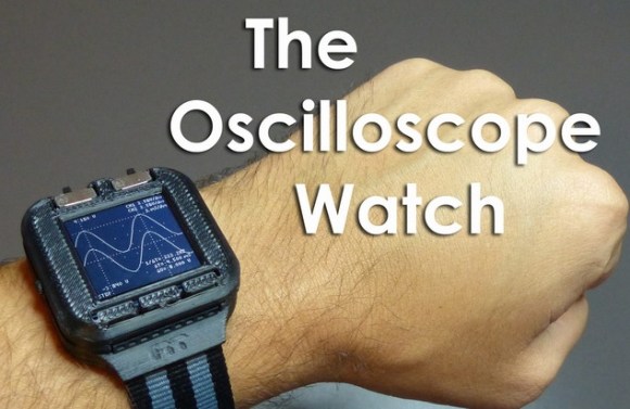
Calculator watches were the Geek cred of the 80’s. Today everyone is getting smart watches. How can the hip Geek stay ahead? [Gabriel Anzziani] to the rescue with his Oscilloscope Watch! [Gabriel] has made a cottage industry with his micro test tools. We’ve featured his Xprotolab and Xminilab on here on Hack a Day more than once. The Oscilloscope Watch basically takes all the features of the Xprotolab and squeezes them down into a wrist watch.
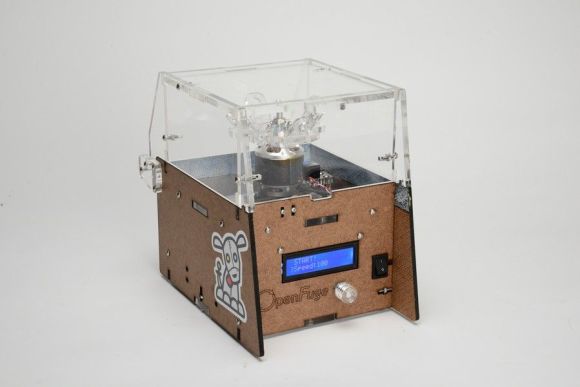
The Oscilloscope Watch includes an oscilloscope, a logic analyzer, an arbitrary waveform generator, and of course it tells time. The Oscilloscope Watch’s processor is the AVR XMega128. [Gabriel] has even included a link to the schematics (PDF) on his Kickstarter page. We really like that 3D printed case, and hope [Gabriel] opens up his CAD designs for us to work with.
Like its predecessors, the Oscilloscope watch won’t be replacing your Tektronix scope, or even your Rigol. Much like a Swiss army knife or Leatherman tool, the Oscilloscope Watch packs a bunch of tools into a small package. None of them are as good as a full-sized tool, but in a pinch they will get the job done. If you are wondering where the probes connect. [Gabriel] states on the Kickstarter page that he will design a custom 9 pin .100 connector to BNC adapter to allow the use of standard probes.
The screen is the same series of Sharp Memory LCD’s used in the Pebble watch. [Gabriel] chose to go with the FPC version of the Sharp LCD rather than the zebra connector. We’ve learned the hard way that those flex circuits snap at the LCD glass after only a few flexes. Hopefully this won’t impact the hackability of the watch.