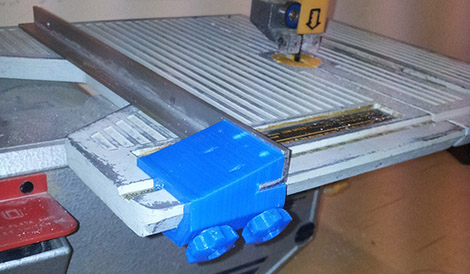
This Panavise Jr. Speed Winder Should Be In Every Maker’s Toolbox

panavise-jr-power-winder

Like many makers, [Chris] has a Panavise Jr. on his workbench that he uses for just about everything. The tiny vise is great for all sorts of tasks, and is often considered an indispensable tool. The only problem with the vise is the amount of time it takes to open and close the thing.

[Chris] estimates that it takes somewhere between 2 and 3 million turns of the crank to move the vise’s jaws from fully open to the fully closed position. He figured that his drill is far better at mindlessly turning circles than he is, so he sat down and designed a bit in Google Sketchup to spin the vise’s crank knob.

He fired up his MakerBot and printed out his first “Speed Winder” drill bit. It was decent, but he thought it could be better. After a handful of revisions, he was finally happy with the results. He says it works great, and has posted the model on Thingiverse so that everyone can print one of their own.

Continue reading to see how [Chris] created the bit along with how much time this thing saves him. Continue reading “This Panavise Jr. Speed Winder Should Be In Every Maker’s Toolbox”

HEX Out Reveals The Secrets Your Data Bus Holds

[Quinn Dunki] is looking to augment the tools she has available at her electronics bench and built the HEX Out as a mock-logic sniffer. The device reads 8 or 16-bit inputs, showing the current state of those connections on a 7-segment display. This requires that you’re comfortable reading Hex codes, but if you’re not it’s almost like studying flash cards; before long you’ll be able to read them without thinking about it.

She’s blogging about the design and build process in three parts. The link above is the first installment where she shares the development process for the top layer which hosts the display hardware. The other two parts should be up for your enjoyment in the next couple of weeks.

You’ll notice her design on this portion of the project still requires a lot of point-to-point soldering, even though she etched her own circuit boards. We didn’t look too closely, but it seems this would be worth going to the trouble of etching a double-sided board if you can.

UPDATE: Part Two is now available

DIY Spot Welder Can Join Anything Together, Even Copper

copper-spot-welder

Hackaday reader [David] was looking for a cheap and easy way to spot weld copper tabs together. As he notes in his writeup, the properties of copper which are most enticing, such as high thermal capacity, make welding it all that more difficult. His home-brew method of spot welding is admittedly quick and dirty, but it does get the job done quite well.

He started off with an array of four 2.5V @ 2600 Farad ultra capacitors, which provide the high current required to do copper spot welding properly. They are wired in series and connected to his electrodes using heavy gauge wire. The graphite-tipped electrodes were an interesting DIY job themselves, cleverly constructed using copper tubing and a graphite block. The most simple/dangerous/clever part of the whole rig is his trigger mechanism, which consists of a pair of copper blocks that he bangs together manually to complete the circuit.

[David] is well aware that the setup is just a touch rough, but according to him it makes great welds, and it’s only a proof of concept at this point. He has a hefty list of improvements to make for the final version, including a different switching method among a few other safety precautions.

Millivolt Meter Nixie Clock

Surprisingly, up until a year ago, [Jimmy] hadn’t seen a Nixie tube. Awful we know, but he has come around to the beauty of glowing numbers in a tube. He recently found an old millivolt meter in a junk pile that used Nixie tubes. The wondrous orange glow beckoned him, so [Jimmy] decided to build a clock.

Just about all of the Nixie clocks we’ve seen (including non-clock builds) rely on building a controller for the Nixie tubes. The controllers range from Nixie Arduino shields to the good ‘ol 74141 IC. [Jimmy] realized he didn’t need to bother with controlling the tubes in an already functional millivolt meter – he only needed to send the right voltage.

For his clock build, [Jimmy] used an Arduino to output a voltage through a bunch of resistor dividers. For example, if the time is 12:30, the output voltage will be 12.30mV. Using this technique, the values for the needed resistors don’t exist, so a little bit of PWM means the Arduino keeps fairly good time.

There’s one added bonus of [Jimmy]’s clock – because the voltage varies around 0.01mV, the finished project acts like a digital version of Lord Vetinari’s clock. It may not be perfect, but at least a nice piece of equipment was saved from the trash.

Cellphone Microscope For About $20

Medical-grade microscope photography for $20 might be a game changer in areas where medical services are unavailable. This particular hack uses an iPhone’s 2 megapixel camera, as well as a tiny glass marble, to magnify a sample to about 350 times its actual size. The two images seen on the left are red blood cells photographed with the improvised microscope. The main issue with this magnification method is a very thin plane of focus that is overcome with processing in software.

This makes us think of the microscope hack that shined a laser through a droplet of water, to project the image on a wall. The concept was later refined to work with samples on glass slides. There are a couple of distinct advantages to using this cellphone-based method. First, the sample can be seen with its true colors. Second, you not only magnify the sample, but you have a digitized image already on a device that connects to the Internet. If you’re trying to make a medical diagnosis this can easily be sent to a qualified professional for analysis.

The team that came up with this technique also figured out how to build a cellphone-based spectrometer for just a few bucks. The image in the upper right is the result of that hack. Both have a step-by-step build guide on the page linked at the top. The microscope is just a glass bead in a piece of rubber, as seen here. The spectrometer is a bit more involved.

[Thanks Fabien]

Multicolor 3D Prints The Hard Way

After drooling over the Makerbot dual-head extruder, [Brett] decided to get off his duff and make a proper multi-color print.

[Brett] has been making a few bottle openers for friends and has been successfully experimenting with switching filaments in the middle of a print. For his “Saturday Killer” bottle opener, he decided to push multicolored prints to the limit. For the “Saturday Killer,” [Brett] decided to print an abridged version of the classic Simpsons quote, “Beer, the cause of, and solution to, all of life’s problems” on the side of a bottle opener in 4 different colors.

The files necessary to print the Saturday Killer were generated in OpenSCAD. The general principle behind the design is to generate separate .STL files for the bottle opener and the sides, split those files into 2-layer chunks, and print those files while constantly adjusting the z-height. It’s not called the Saturday Killer for nothing, so [Brett] had to change the color of his filament 25 times.

A much simpler version of a complex multi-color print is [Brett]’s Shepard Fairey inspired self-portrait. Still, we’re thinking a dual head extruder is somewhere in [Brett]’s future. At least he’s got the technique down.

Modding An Inkjet For PCB Production

Like all of us, [Ryan] is tired of waiting for board production houses. To reduce some of that turnaround time, he modded an Epson inkjet into a PCB printer. The Instructable of his build is extremely thorough and it looks like he’s getting some quality boards out of his project

The build started off by disassembling an Epson C86 printer he had lying around the house. Going with an Epson printer is important – Epsons have a piezo print head accepts ink that would clog other printers. After tearing all the plastic off his printer, [Ryan] set to work raising the printer (or lowering the bed, whatever) and was off to the races.

The cartridges were filled with etch-resistant yellow ink and a piece of copper clad put onto the printer. After printing, [Ryan] etched his board in ferric chloride. Sadly, he’s getting small pinholes in his traces where a bit of the ink was eaten during etching. He’s tried HCl and Peroxide, but those turn his boards into green junk.

If you’ve got any tips to help [Ryan] out, leave them in the comments. Before that, check out the printing demo [Ryan] put up.

Continue reading “Modding An Inkjet For PCB Production”