
Regular Hackaday readers will be familiar with the work of Boldport’s [Saar Drimer] in creating beauty in printed circuit board design. A recent work of his is the Widlar, a tribute to the legendary integrated circuit designer [Bob Widlar] in the form of a development board for his μA723 voltage regulator chip.
The μA723 is a kit of parts from which almost any regulator configuration can be made, but for [tardate] it represented a challenge. The μA723 is so versatile that what you can create is only limited by the imagination of the builder. Having done the ordinary before, [tardate] looked toward something unconventional.
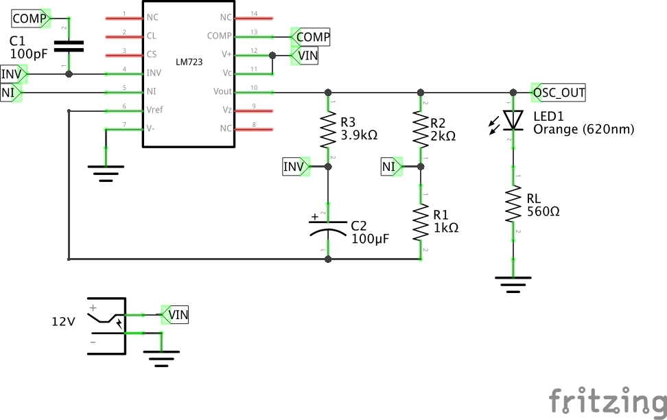 The result is modest, a simple LED flasher using the error amplifier as a not-very-good op-amp, building an oscillator at a frequency of about 2 Hz. This is pretty neat and if you are used to the NE555 as the universal integrated circuit, perhaps it’s time to set it aside for the obviously far-more-useful μA723.
Here at Hackaday we harbour at least one fan of the μA723, not to mention also of artful PCBs. If the Widlar looks familiar, we featured the switch mode regulator from the μA723 data sheet on it a few months ago.
Disclosure: [Jenny List] wrote the documentation for Boldport’s Widlar kit.