Op-Amp Challenge: A Logic-Free BCD

Of digital electronics, a wise man once said that “Every idiot can count to one.” Truer words have rarely been spoken, because at the end of the day, every digital circuit is really just an analog circuit with the interesting bits abstracted away. And to celebrate that way of looking at things, we’re pleased to present this BCD to seven-segment converter that uses no logic chips.

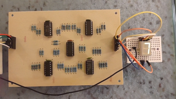
With cheap and easily available chips that perform this exact job, it might seem a little loopy to throw 20 LM324 op-amps at the job. But as [gschmidt958] explains, this is strictly for the challenge, plus it made a nice entry in the recently concluded Op-Amp Challenge contest. His work began in simulation, exploring op-amp versions of the basic logic gates — NAND, AND, OR, and NOT — all of which rely on using the LM324s as comparators. There were real-world curveballs, of course, not least of which was running out of the 10k resistors used for input averaging. Another plot twist was running out of time to order a PCB, which required designing one using MS Paint and etching it at home.

The demo video below shows the circuit at work, taking the BCD output of a 74HC393 counter — clocked by a 555, naturally — and driving a seven-segment LED.  It’s honestly a lot of work for such a simple task, but there’s something satisfying about the whole project. We think [Widlar] would be proud.

Continue reading “Op-Amp Challenge: A Logic-Free BCD”

Flashing An LED The Widlar Way

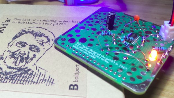
Regular Hackaday readers will be familiar with the work of Boldport’s [Saar Drimer] in creating beauty in printed circuit board design. A recent work of his is the Widlar, a tribute to the legendary integrated circuit designer [Bob Widlar] in the form of a development board for his μA723 voltage regulator chip.

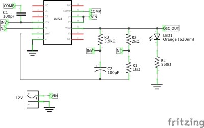
The μA723 is a kit of parts from which almost any regulator configuration can be made, but for [tardate]  it represented a challenge. The μA723 is so versatile that what you can create is only limited by the imagination of the builder. Having done the ordinary before, [tardate] looked toward something unconventional.

The result is modest, a simple LED flasher using the error amplifier as a not-very-good op-amp, building an oscillator at a frequency of about 2 Hz. This is pretty neat and if you are used to the NE555 as the universal integrated circuit, perhaps it’s time to set it aside for the obviously far-more-useful μA723.

Here at Hackaday we harbour at least one fan of the μA723, not to mention also of artful PCBs. If the Widlar looks familiar, we featured the switch mode regulator from the μA723 data sheet on it a few months ago.

Disclosure: [Jenny List] wrote the documentation for Boldport’s Widlar kit.

The UA723 As A Switch Mode Regulator

If you are an electronic engineer or received an education in electronics that went beyond the very basics, there is a good chance that you will be familiar with the Fairchild μA723. This chip designed by the legendary Bob Widlar and released in 1967 is a kit-of-parts for building all sorts of voltage regulators. Aside from being a very useful device, it may owe some of its long life to appearing as a teaching example in Paul Horowitz and Winfield Hill’s seminal text, The Art Of Electronics. It’s a favourite chip of mine, and I have written about it extensively both on these pages and elsewhere.

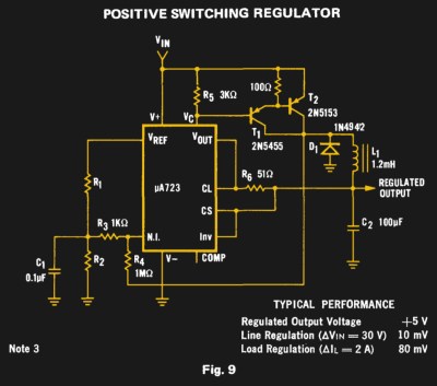
The Fairchild switching regulator circuit. From the μA723 data sheet in their 1973 linear IC databook, page 194 onwards.

For all my experimenting with a μA723 over the decades there is one intriguing circuit on its data sheet that I have never had the opportunity to build. Figure 9 on the original Fairchild data sheet is a switching regulator, a buck converter using a pair of PNP transistors along with the diode and inductor you would expect. Its performance will almost certainly be eclipsed by a multitude of more recent dedicated converter chips, but it remains the one μA723 circuit I have never built. Clearly something must be done to rectify this situation.

Continue reading “The UA723 As A Switch Mode Regulator”