Should you spend some time around the less scientifically informed parts of the internet, it’s easy to find “Free power” stories. Usually they’re some form of perpetual motion machine flying in the face of the laws of conservation of energy, but that’s not to say that there is no free power.
The power just has to come from somewhere, and if you’re not paying for it there’s the bonus. [joekutz] has just such a project, lighting up LEDs with no power source or other active electronics.
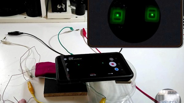
Of course, he’s not discovered perpetual motion. Rather, while an LED normally requires a bit of current to light up properly, it seems many will produce a tiny amount of light on almost nothing. Ambient electromagnetic fields are enough, and it’s this effect that’s under investigation. Using a phone camera and a magnifier as a light detector he’s able to observe the feeble glow as the device is exposed to ambient fields.
In effect this is using the LED as the very simplest form of radio receiver, a crystal set with no headphone and only the leads, some wires, and high value resistors as an antenna. The LED is after all a diode, and it can thus perform as a rectifier. We like the demonstration even if we can’t quite see an application for it.
While we’re no longer taking new entries for the 2025 Component Abuse Challenge, we’ve still got plenty of creative hacks from the competition to show off. We’re currently tabulating the votes, and will announce the winners of this particularly lively challenge soon.