[Ramin Assadollahi] uses his Raspberry Pi Zero W as a self-contained mobile desktop, connecting to it over VNC from another computer when he wants to hack away at some code or work on a new project. But he often found himself wishing there was some convenient way of displaying pertinent into right on the device, such as what IP address the Pi Zero had pulled. Then he found the 2.13 inch e-Paper HAT for the Pi Zero from Waveshare, and it all clicked into place.
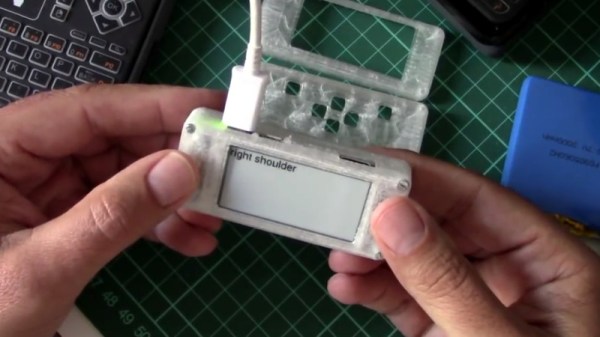
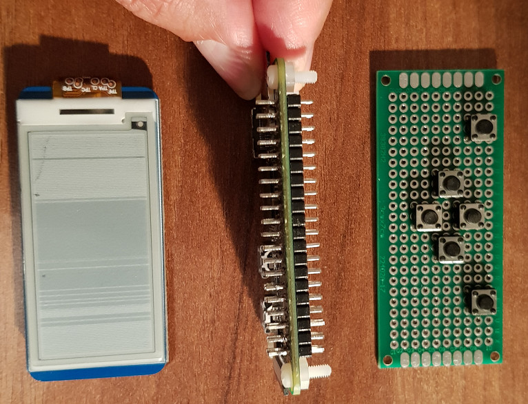 The final device, which he refers to as the StickPi, combines a Pi Zero W, the Waveshare e-Paper display, and a strip of protoboard featuring a few tactile buttons, all inside of a 3D printed case. To really get the most out of the internal volume of his case, [Ramin] soldered the header pins to the Pi Zero in the middle, allowing him to create a space-saving “sandwich” out of all the components.
With the e-Paper display, [Ramin] now has a way to show information on the device itself without having to connect to it over the network. But thanks to the tactile switches on the back connected to the Pi’s GPIO, he also has six programmable buttons that could do anything he wants.
In the most basic implementation, each button could execute a command or script on the Pi. But [Ramin] has something a little more advanced in mind. In the video after the break, he explains that his next step is going to be working on an actual user interface for the Pi’s e-Paper screen, making use of the roughly gamepad style layout of the rear buttons. A “paged” interface with scrolling options would allow the user to perform all sorts of functions quickly and easily, and we’re looking forward to seeing what he comes up with.
This isn’t the first time we’ve seen somebody try to turn the Pi Zero into a more mobile-friendly platform, and the construction method here actually reminds us of a much smaller version of the Zero Phone.
Continue reading “Pocket-size Pi Zero Desktop Features E-paper Display”