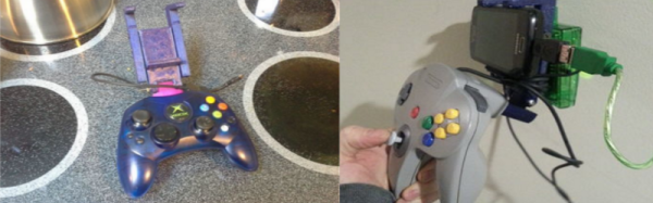
Good Vibrations In 3D-Printed Clay

An engineer with a 3D printer wants everything to be rigid and precise. Wobble induced by flex in the z-axis feedscrews, for instance, makes telltale wavy patterns in the surface that match exactly the screw pitch. Nobody likes those, right? Certainly not an engineer!

good_vibrations-shot0008_thumbnailBut one man’s surface irregularity is another man’s ornamentation. The details we have are sparse, but from looking at the video (also inlined below the break) it’s clear enough: [Olivier van Herpt] and [Ricky van Broekhoven] stuck a vibrating woofer underneath the print bed of their ceramic printer, and use it to intentionally ruin their smooth surface. And they do so to great artistic effect!

We’re not suggesting that you give up entirely on your calibrations, but we do appreciate a little out-of-the-box thinking from time to time. But then our internal engineer raises his head and we wonder if they’re linking the pitch of the woofer to the feed rate of the print head. Your thoughts in the comments?

Continue reading “Good Vibrations In 3D-Printed Clay”

The OpenR/C Project

The Open RC Truggy that started it all.

[Daniel Norée] started the OpenR/C project back in 2012 when he bought a Thing-O-Matic. In search of a project to test out his new printer, he set his sights on a remote controlled car, which as he put it,”… seemed like the perfect candidate, as it presents a lot of challenges with somewhat intricate moving parts along with the need for a certain level of precision and durability.

After releasing his second design, the OpenR/C Truggy, he realized a community was forming around this idea, and needed a place to communicate. So, he created a Google+ group. Today, the Truggy has been downloaded over 100,000 times and the Google group has over 5,000 members. It’s a very active community of RC and 3d printing enthusiasts who are testing the limits of what a 3d printer can do.

Continue reading “The OpenR/C Project”

Super Sizing The Printrbot Metal Simple

The Printrbot Simple Metal is a good 3D printer, with a few qualifications. More accurately, the Printrbot Simple Metal is a good first 3D printer. It’s robust, takes a beating, can produce high-quality prints, and is a great introduction to 3D printing for just $600. There are limitations to the Printbot Simple Metal, the most important is the relatively small 150mm cubed build volume.

[ken.do] wanted to print large parts, specifically scale aircraft wings and panels. While the Printrbot can’t handle these things normally, the design of the printer does lend itself to increasing the size of the build volume to 500mm long and 500mm high.

Increasing the build height on the Printrbot is as simple as adding two longer smooth rods and a single threaded rod to the Z axis. Increasing the X axis is a bit trickier: it requires a very flat sheet that doesn’t warp or bend over 500 mm, even when it’s being supported in different places. [ken.do] is engineering stiffness into a build plate here. The solution to a huge bed is a two kilogram aluminum bed supported by heavier rails and riding on a massive printed bushing block. Does it work? Sure does.

If you want to print tall objects, the current crop of 3D printers has you covered: just get a delta, and you’re limited only by the length of the extrusion used in the body. Creating big objects in all three dimensions is a marginally solved problem – just get a big printer. Big printers have drawbacks, notably the incredible power requirements for a huge heated build plate.

The ability to print long objects is a problem that’s usually not addressed with either commercial 3D printers or RepRaps. We’re glad to see someone has finally realized the limitations of the current crop of 3D printers and has come up with a way to turn a very good first printer into something that solves a problem not covered by other 3D printers.

Repairing A MakerBot Mightyboard Clone

It can be argued that MakerBot, a company that makes popular 3D printers, hit its pinnacle with the introduction of the Replicator 2. It was designed well and completely open source, including the motherboard that drove the printer – known as the Mightyboard. China quickly picked up on the success of the Replicator 2 and copy/pasted several of their own versions (at a much cheaper sale price). One of these outfits is called Wanhao, and their version of the Replicator 2 is called..wait for it…the Duplicator!

Their version of the Mighyboard is identical to the original, minus a few nickle and dime components. This suggests that Wanhao made an effort to cut as much cost as possible without looking at what functionality they were removing. And anytime a company does this, you can bet the quality of the board manufacturer is at the bottom of the barrel.   [Avrydev] found this out the hard way when he repaired a faulty motherboard from a broken Duplicator.

The board would not connect to the software via USB, and the startup tune pitch was off. [Arvydev] flashed new firmware via ICSP, but that did not help. He eventually clued in on the main crystal for the Atmega processor. A quick swap and presto! The printer is as good as new.

Solder Stencils With A 3D Printer

If you are soldering with paste, a stencil makes life a lot easier. Sure, you can apply paste by hand with a syringe, but a modern PCB might have hundreds or even thousands of pads. Like a lot of us, [Robert Kirberich] doesn’t like paying to have stencils made and he wondered if he could use his 3D printer to make stencils. He found the answer was yes.

Continue reading “Solder Stencils With A 3D Printer”

Filament Thickness Sensors, What Are They And What Are They Good For?

I keep up with the trends in 3D printing reasonably well. The other day my friend mentioned that filament thickness sensing had been added to the latest version of the Marlin firmware. I had no idea what it was, but it certainly sounded cool. I had to find out more.

In industrial settings, filament is made by pulling extruding molten plastic at a certain speed into a cooling bath. The nozzle for 2.85mm filament and 1.75 mm filament is actually the same size, but the filament is stretched more or less as it leaves the nozzle. By balancing these three variables the extrusion machine can produce any size filament desired. Like any mechanical system, it needs constant adjustment to maintain that balance. This is usually done by measuring the filament with a laser after it has cooled, and then feeding this information back into the system. The better filament manufacturers have multiple lasers and very fast feedback loops. Some of the best offer +-0.04mm or less variation in thickness between any two points on the filament. Some of the worst have larger errors such as +-.10mm. Because the plastic is fed into the extruder at a fixed linear speed, this makes a variation in the volume of the plastic coming out of the nozzle per second. With the best we see a 4.41% variation in the volume of plastic extruded. With the worst we start to see 10.51% or more.

FIlament variation showing up as a cosmetic defect.
Filament variation showing up as a cosmetic defect.

A printer is dumb. It works under the assumption that it is getting absolutely perfect filament. So when it gets 10.51% more plastic, it simply pushes it out and continues with its life. However, if the filament is off enough, this can actually show up as a visible defect on the print. Or in worse cases, cause the print to fail by over or under extrusion of plastic.

So, what does a filament thickness sensor do to correct this issue? To start to understand, we need to look at how the filament is dealt with by the software. When the slicer is compiling the G-code for a 3D print, it calculates the volume of plastic it needs in order to deposit a bead of plastic of a certain width and of a certain height per mm of movement. That was a mouthful. For example, when a printer printing 0.2mm layers moves 1mm it wants to put down a volume that’s 1.0mm long x 0.4mm wide x 0.2mm high. The filament being pushed into the nozzle has a volume per mm determined by the diameter of the filament.

(\pi (radius_{filament})^{2}*length_{filament extruded})=volume

The volume out per mm of filament in.

(layer_{height}*layer_{width}*length_{move}) = volume

The equation we are trying to balance.

Our goal is to integrate the thickness sensor into these functions to see what the thickness sensor is doing. This is a linear equation, so there’s nothing fancy here. Now, the layer height, layer width, and length of the move are determined by settings and model geometry respectively. These are fixed numbers so we don’t care about them. That leaves us the diameter of the filament and the length of filament extruded. As we mentioned before, typically the filament is assumed to be a fixed diameter. So all the software has to calculate is the length of filament that needs to be extruded per mm of combined movement in the x and y so that our volumes match.

But, we know that one of these variables is actually changing per millimeter as well. The filament diameter! So now we have a problem. If the filament diameter is changing all the time, our equation will never balance! In order to fix this we can add a multiplier to our equation. Since we have no control over the width of the filament we can’t modify that value. However, if we know the width of the filament, and we know the value its supposed to be, we can change the length of the filament extruded. This is because unlike the filament, we have control over the stepper motor that drives the extruder. This value is called the extrusion multiplier, and its determination is what the thickness sensor is all about.

So all the filament sensor does is measure the filament’s current diameter. It takes expected diameter and divides it by the value it just measured to get a simple percentage. It feeds that number back into our system as the extruder multiplier and slows or speeds up the stepper motor as needed. Pretty simple.

2016-01-26_00h08_00
Shadows on the sensor from [inornate]’s variation.
There are a few thickness sensors being toyed with right now. The first, as far as I can tell; let me know if I am wrong in the comments, was by [flipper] on thingiverse. He is in his third version now. The sensor works by casting a shadow of the filament as it passes by onto an optical sensor. The firmware then counts the pixels and works backwards to get the diameter. This value is sent to the Marlin firmware on the printer which does the rest. As is usual and wonderful in the open source community, it wasn’t long before others started working on the problem too. [inoranate] improved on the idea by casting more shadows on the sensor. The technique is still brand new, but it will be interesting to see what benefits it reaps.

Now comes the next question,”Is it worth upgrading my printer with a thickness sensor?” If you typically run poor filament, or if you extrude your own, yes. The current sensors can only measure +- .02mm. So for the best filament, you won’t really see a difference, but for worse stuff, you might. The latest firmware of the Lyman filament extruder, for making your own filament, also supports these sensors, letting you feed back into your production system like the industrial machines. All in all a very interesting development in the world of 3D printers.

Fully Printed CNC On An IKEA Table

It seems that many 3D printer owners just aren’t getting the same buzz they used to off their 3D printers, and are taking steps to procure heavier machines. And making them in their home laboratories with, you guessed it, their 3D printers.

Following the pattern, [Michael Reitter], designed a 3D printable CNC around a IKEA MALM table. In order to span the length of the table for his X axis, he came up with a very cool looking truss assembly. The linear rails rest on top of the truss, and a carriage with the Z axis rides on the assembly. The truss has enough space in the center of it to neatly house some of the wiring. The Y-xis mounts on the side of the table.

Overall the mechanical design looks pretty solid for what it is, with all the rails taking their moments in the right orientation. We also like the work-piece hold downs that slide along the edge of the table. It even has a vacuum attachment that comes in right at the milling bit.

We’re not certain how much plastic this build takes, but it looks to be a lot. Monetarily, it will probably weigh in at a bit more than some other options. As many in the 3D printing world are discovering, sometimes there’s no reason not to leverage more mature industrial processes for lower cost large gains in accuracy and strength. Though, it’s pretty clear that one of the design goals of this project was to see how much one can get away with just a 3D printer, and we certainly can’t deny the appealing aesthetic of this CNC.

Video of it in action after the break.

Continue reading “Fully Printed CNC On An IKEA Table”