Nixie Inspired 7 Segment Display

The supply of Nixie tubes from east European stock piles is still enough to keep their prices down. But once those start dwindling, prices will move north. Besides, if you want to use them, you need to work with high voltage supplies and worry about not getting zapped while trying to debug a circuit. [FilleK] had some time to spare and decided to build a cheaper substitute for a real nixie tube using a regular 7 segment LED display.

We have already seen this hack before, in the Arduino-based ENIGMA replica. But [FilleK] improved on that by adding an extra LED to simulate the radiant glow typical of Nixie tubes. His project log describes the fairly straightforward process using parts that can be found easily. A piece of plastic, painted in a shade of copper and fixed around the 7 segment display, acts as a nice baffle to contain and reflect the ambient glow of the back-light LED. A nice improvement would be to add a random flicker to the background LED. Maybe add an Octal socket (the decimal point had to be nixed though!), and cap it in a proper glass tube. If you’d rather work with the real McCoy, check out our archives.

Master Clock Keeps Time For All Other Clocks

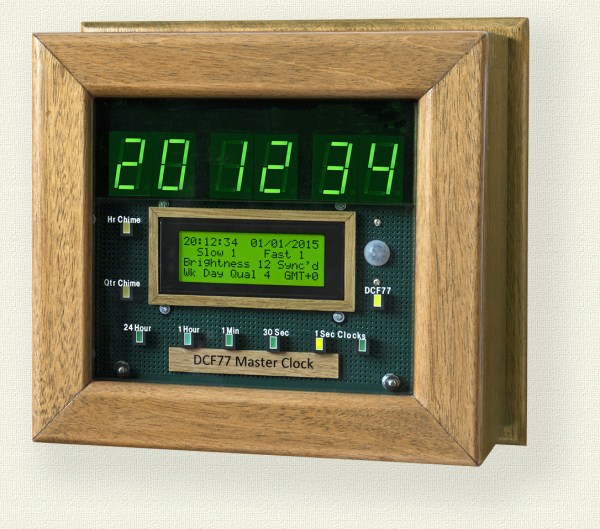
[Brett] just finished construction and long-term testing of this extremely accurate timepiece. It keeps such great time by periodically syncing with the atomic clock in Mainflingen, Germany.

The core of the project is an ATMega328 which uses the new DCF77 library for decoding the signal broadcast by an atomic clock. The libraries written by Udo Klein significantly increase the noise tolerance of the device reading the signal, but they will not work with any project that use a resonator rather than a crystal.

In the event of a complete signal loss from the atomic clock, the micro driving the clock also has a backup crystal that can keep the clock running to an accuracy of within 1 second per day. The clock can drive slave clocks as well, using pulses with various timings depending on what [Brett] needs them to do. The display is no slouch either: six seven-segment displays show the time and an LCD panel reads out data about the clock. It even has chimes for the hour and quarter hour, and is full of many other features to boot!

One of the most annoying things about timekeeping is daylight savings time corrections, and this clock handles that with a manual switch. This can truly take care of all of your timekeeping needs!

Mario Doorbell Guaranteed To Drive A-You A-Crazy

marioDoorbell

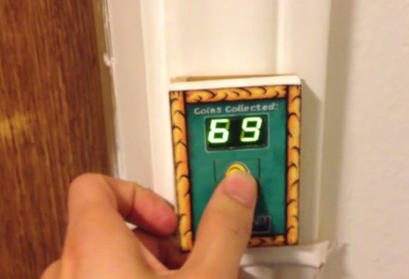
Is your doorbell not exciting enough for your guests? [Joe] wanted to provide a little entertainment for his visitors, so he redesigned his doorbell with a Mario theme.

Whenever someone presses the button—which carries the Mario coin image—the segment display increments and the Mario coin sound plays. To add variety, the life-up sound plays at every 10 coins and the mushroom upgrade sound plays upon reaching 100. [Joe] tried putting the life-up sound at its appropriate 100’s place and the mushroom sound at every 10, but he decided the brevity of life-up was more tolerable in the 10’s slot.

The project was divided into two components. The door button has a PIC16F628A microcontroller with a dual 7-segment LED display, a button, and a homemade circuit board. All this lives in a simple box covered by a Yoshi’s Island-themed decal. The button’s board connects to a separate ringer board—based around a PIC16F87—with a MCP4822 DAC and a 25LC1024 EEPROM. Button presses on the first board prompt a request for a sound clip read on the EEPROM. Keep clicking for a demo video below.

Continue reading “Mario Doorbell Guaranteed To Drive A-You A-Crazy”

504 Segment Clock

FIveOfour_01_13

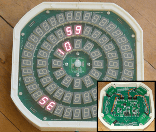
Trying to reinvent the clock has been done over and over again, but it’s always fun to see how over-engineered and complex these designs can get. [Bertho’s] last working clock in his house was the built-in clock on the VCR, so he decided it was finally time to build his own 504 Segment clock.

Yep, that’s right, 504 Segments! This clock uses 72 7-Segment displays to tell time. The video after the break shows the clock in action, but time is read by looking at each ring of displays: outer=seconds, middle=minutes, and inner=hour. [Bertho] could’ve just stopped there, but he decided to load the display up with sensors, so hand-waiving can change modes, and brightness can be regulated based on ambient light conditions. And since he has individual control over each segment, he has implemented some pretty cool mind-melting animations. Oh, and did we mention that the display synchronizes with an NTP server?

The display is divided into 4 quadrants, each containing 18 7-Segment displays. The control architecture is interesting because each quadrant is controlled by its own PIC microcontroller, which handles the continuous multiplexing and modulation of the 18 7-Segment displays.  A main control board contains another (more powerful) PIC to update the 4 quadrants via a serial bus. This board also handles the Ethernet connection, sensor interface, and local RTC(real time clock). This isn’t the first time we’ve seen [Bertho’s] amazing work, so make sure you check out his useless machine and executive decision maker.

Continue reading “504 Segment Clock”

A Transparent 7-Segment Display

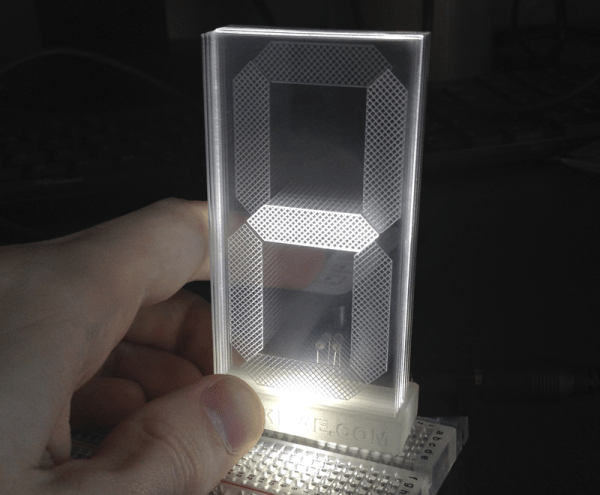
Though [Connor] labels it as a work in progress, we’re pretty impressed with how polished his transparent 7-segment display looks. It’s also deceptively simple.

The build uses a stack of seven different acrylic panes, one in front of the other, each with a different segment engraved onto its face. The assembly of panes sits on a small mount which is placed over seven rows of LEDs, with 5 LEDs per row. [Connor] left an air gap between each of the seven individual acrylic panes to clearly distinguish which was lit and to match the separation of the LED rows. To display a number, he simply illuminates the appropriate LED rows, which scatter light across the engraved part without spilling over into another pane.

You can find a brief overview and some schematics on [Connor’s] website, and stick around for the video demonstration below. We’ve featured [Connor’s] work before; if you missed his LCD data transfer hack you should check it out!

Continue reading “A Transparent 7-Segment Display”

Controlling High Voltage 7-Segment Displays

highvoltage7seg

The MAX7219 is one of those parts in your bin that has a “done and done” attitude. In case you’re unfamiliar, this chip can be used to control 7-Segment displays, 8×8 Matrix displays, or even a pile of random LEDs. You talk to it via a simple serial interface and it handles the tasks you don’t want to fuss with, such as multiplexing and modulation. Not all displays are alike, however, so [Raj] wrote in to show how he used the MAX7219 to control high voltage 7-segment displays.

The spec on the MAX7219 only allows an input voltage of 5V, which limits the driver output to around 4V and can cause problems when using large displays that series-connect LEDs internally. [Raj’s] solution allows the MAX7219 to control displays with combined forward voltages of up to 24V, and as an added bonus, the circuit maintains compatibility with existing microcontroller libraries. We imagine this could be a nifty trick to keep on hand the next time you need to control large scoreboard displays.

The circuit works with the help of intermediate drivers to essentially level-shift the voltage to the display, which both provides the high voltage and protects the MAX7219’s inputs. One of the drawbacks of this circuit is losing the MAX7219’s constant current feature, requiring that each segment connection includes a current-limiting resistor. We appreciate this design’s attention to default states, because you wouldn’t want all of your LEDs turning ON during boot-up!

Turning Cheap Voltmeters Into I2C Displays

Voltmeter I2C Displays

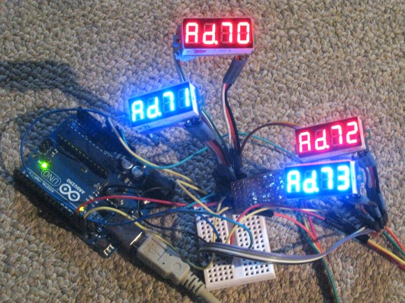
[Tom] needed 8 displays for a project. He wanted to to control them over I2C, and was trying to reduce cost. Some vendors make I2C controllable seven segment displays, but they cost about $10 each. [Tom] figured he could hack cheap voltmeters to get the same results for about $3 a pop.

The voltmeters that [Tom] bought used a 8 bit STM8S003F3P6 microcontroller. He reverse engineered the device and re-created the schematic to find out where the I2C and programming pins would be. Then he hooked it up to a STM8 Discovery development board, which has an integrated programmer.

With the hardware figured out, it was time for new firmware. Fortunately, [ba0sh1] had already written firmware for a similar purpose which could easily be adapted. The code implements a software I2C slave, which reads data off the bus and displays it. It’s all available on Github.

The end result is a I2C controlled display for a third of the cost. Next time you need a bunch of these in a project, consider picking up some cheap voltmeters.