New PCB Revives Ancient Bubble LED Displays

For those of us who remember LED calculators, the HP 5082-7400 series red “bubble” displays hold a special charm. Available in 3, 4, or 5-digit varieties, these multiplexed 7-segment displays provided countless hours of entertainment to those who would spell upside-down words on their pocket calculators. In case you happen to be lucky enough to have access to a few of these beautiful vintage display sticks, [Gigawipf] has designed a small driver PCB that lets you easily interface them to a modern microcontroller.

At the heart of the board, aimed at either the 5082-7405 or 5082-7415 5-digit modules, are a pair of 74HC595 shift registers in tiny QFN packages. Five lines from one register drive one of the common cathodes for the selected digit, while the other register drives the eight anode lines through 330-Ohm resistors. The boards are slightly smaller than the width of the displays allowing you to stack them seamlessly for more digits, and eight header pins on each allow you to plug them into solderless breadboards for prototyping. The result is easy to drive with some simple code, and [Gigawipf] provides an example for Arduino as part of the project. The Eagle design files are supplied, as well as Gerbers for those who just want to have some boards made. This sounds like a great way to get some of these vintage displays going again.

If you can’t find any of these displays to play, with, you can try making some larger digits from individual surface-mount LEDs.

Make Your Own Old School LED Displays

We live in an era in which all manner of displays are cheap and readily available. A few dollars spent online can net you a two-line alphanumeric LCD, a graphical OLED screen, or all manner of other options. Years ago however, people made do with little monolithic LED devices. [sjm4306] wanted to recreate something similar, and got down to work (Youtube link, embedded below).

The resulting device uses 0603 sized SMD LEDs, soldered onto a tiny PCB. 20 LEDs are used per digit, which can display numbers 0-9 and letters A-F. The LEDs are laid out in a pattern similar to Hewlett-Packard designs from years past. This layout gives the numerals a more pleasant appearance compared to a more-classic 7-segment design. Several tricks are used to make the devices as compact as possible, such as putting vias in the LED pads. This is normally a poor design technique, but it helps save valuable space.

[sjm4306] has developed a breadboard model, and a more advanced version that has a pad on the rear to mount a PIC16F88 microcontroller directly. We look forward to seeing these modules developed further, and can imagine they’d prove useful in a variety of projects.

For reference, check out these Soviet-era 7-segment displays. Video after the break.

Continue reading “Make Your Own Old School LED Displays”

Addressable 7-Segment Displays May Make Multiplexing A Thing Of The Past

[Sean Hodgins] has a knack for coming up with simple solutions that can make a big difference, but this is one of those “Why didn’t I think of that?” things: addressable seven-segment LED displays.

[Sean]’s design is basically a merging of everyone’s favorite Neopixel RGB LED driver with the ubiquitous seven-segment display. The WS2811 addressable RGB driver chip doesn’t necessarily have to drive three different color LEDs – it can drive three segments of the same display. With three of the chips on a single board, all seven segments plus the decimal point of a display can be controlled over a single data line. No more shift registers, no more multiplexing. And as a nice touch, individual displays can be ganged together with connectors on the back of each module. [Sean] has some code to support the display but is looking for someone to build a standalone library for it, so you might want to pitch in. Yes, he plans to sell the boards in his shop, but as with all his projects, this one is open source and everything you need to build your own is up on GitHub. The brief video below shows a few daisy-chained displays in action.

Like many of [Sean]’s designs, including this Arduino rapid design board, this is a simple way to get a tedious job done, and it wrings a lot of functionality from a single IO pin.

Continue reading “Addressable 7-Segment Displays May Make Multiplexing A Thing Of The Past”

7 Segment Clockwork Display Made From Cardboard

We’ve seen a variety of oddball 7-segment displays in the past, but this one uses a new material: both for the display and the mechanical mechanism that drives it; cardboard. Yup, the whole thing is made from cardboard, wood and a few rubber bands. [The Q] shows how he put together in this nice video, starting from first principles that show how the segments are made: simple pieces of cardboard painted on one side with fluorescent paint. A piece of wood pushes the element out to blank it, and each element is connected to a cam wheel that pushes the wood in or out.

The really clever bit is that [The Q] mapped digits 0 – 9 onto a matrix for which of the 7 segments is “on” or “off”. He then used this information to create a stack of 7 cams on a central axle. As you rotate the axle, the cams turn, moving the wooding arms. The arms then cause the elements to flip as they count up through the digits. In essence, he engineered a physical decimal to 7 segment decoder, much like the electronic one inside the SN74LS47. The whole assembly is capped by a knob that indicates which digit is currently displayed. If mechanical displays like this are your thing, check out this one made from LEGO parts, or this awesome 3D printed creation.

Continue reading “7 Segment Clockwork Display Made From Cardboard”

A Display Made From Shoelaces

In our time here at Hackaday, we have seen many display builds, but this one from [Brian Lough] has to be a first. He’s created a 7-segment display made from shoelaces, and it works rather well.

Before you imagine the fabric cords you’re used to with your trainers, it’s worth explaining that these aren’t shoelaces in the traditional sense, but transparent light pipe taken from commercially available light-up shoelaces. He’s created a 3D-printed frame with receptacles for each end of the light pipe sections he’s used as segments, and spaces for addressable LEDs on the rear. He makes no bones about his soldering job being less than perfect, but the result when hooked up to an Arduino is very impressive. A large 7-segment LED display that’s visible in the glare of his bench lighting and not just in subdued illumination. Future plans include replacing the messy wiring with stripboard sections for a better result.

This isn’t the first 7-segment display using a light pipe that we’ve seen here at Hackaday, a previous effort used a more novel substance. But perhaps this Nixie-inspired take on the same idea also deserves a mention.

Continue reading “A Display Made From Shoelaces”

Seven-Segment Flip Clock Display Finally Finished

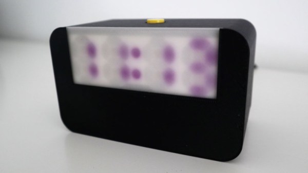
Earlier this year, we mentioned in a Hackaday Links article that [Spencer Hamblin] was in the process of building a seven-segment flip clock. Well, it’s finally finished, and it looks great!

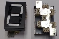
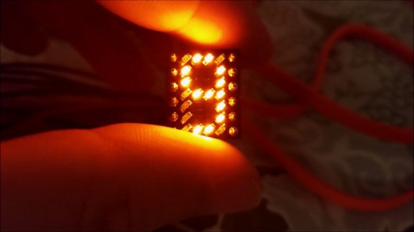
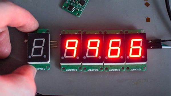
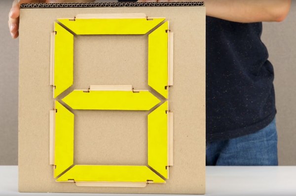
Vintage seven segment digits make up the display. These digits work the same way that flip-dot displays work – current through each segment’s coil creates a magnetic field which causes the segment to flip over. Current in the other direction creates the opposite magnetic field and flips the segment the other way. On these digits, there are three connections on the coils. The middle one is power and the other two are used to enable and disable the segment – ie., flip it one way or the other. To save on pins on the microcontroller, [Spencer] connected all the middle coil pins together on a digit. Each coil can be powered using a single pin on the microcontroller. Similarly, the segments for each digit are connected together as well, so one pin on the micro controls the same segment on each of the digits. The microcontroller in question is the AVR ATMega48.

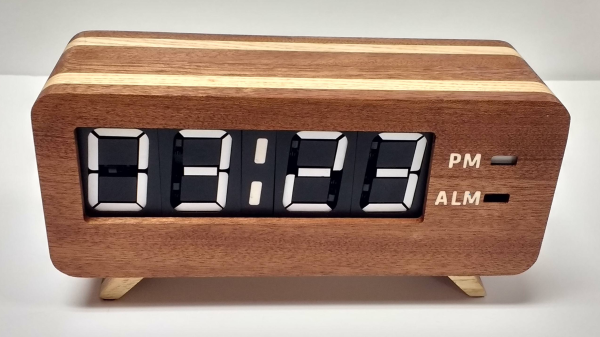
There are two parts of the clock face left to do: AM/PM and whether the alarm is set or not. [Spencer] used a fifth digit, slightly offset, for those – the top and middle segments are used.

For the housing of the clock, [Spencer] used layers of offsetting colored wood. The wood (sapele and ash) were CNC cut and aligned. The back plate, also made from wood, holds buttons for setting the time and alarm, as well as some LEDs for what [Spencer] calls the “daylight alarm.” A capacitive sensor on the top of the unit (inside the wooden case) is used to turn the alarm off.

The result, after sanding and shellacing, looks amazing. [Spencer] nailed the art-deco look he was going for. There are plenty of pictures and the circuit designs, schematics and code are on [Spencer]’s Hackaday.io page, and you can find the Hackaday links post here. This is a complete log of a project we mentioned earlier on Hackaday, here, but there are other mechanical flip display clock projects, such as this DIY mechanical flip seven-segment prototype, or, you could create your own (really big) clock using this Lego mechanical seven-segment display.

via Reddit.

Large Seven-Segment Clock Build Takes Time To Perfect

[Kevin Rye] built a discrete TTL based seven-segment clock, and he wasn’t too happy with the ugly insides compared to the nice enclosure he built for it. He embarked on creating another large seven-segment clock to put inside that enclosure.

Clocks, and specifically seven-segment based ones, aren’t anything new to write about. This particular project, which is still work in progress, is interesting. [Kevin] is an experienced hacker, but the problems he encountered and resolved along the way could prove useful to a fellow hacker someday.

To start with, he tried rectifying his old build. But in his own words “You can polish a turd, but it’s still a turd.” Five years later, he’d had enough. He’s built a lot of other clocks, but rather than repurposing them, he decided to start from scratch. He quickly breadboarded an Arduino, some displays and drove them using the Multiplex7seg library. That library supports only four characters, so he was back to the drawing board. With a fresh start, his design is now moving along nicely. For now, he’s designed three boards for the display, two boards for the colons between digits, the main Arduino-clone controller board and a 3D printed front frame to hold the displays. It will be nice to finally see that enclosure receive some fitting occupants and bring this build to closure.