Hack A Mag-Lite To Be Rechargeable

rechargeMaglite

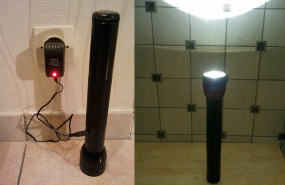
Most tools sport rechargeable batteries these days, but there’s no need to toss that old flashlight: just replace the cells with rechargable ones!

[monjnoux] had a 3-cell D-sized MagLite lying around—though you could reproduce this hack with a 2 to 5 cell model—which he emptied of its regular batteries and replaced with some 11000mAh NiMHs from eBay. The original bulb was also tossed in favor of a 140-lumens LED.

After disassembling the flashlight, [monjnoux] set about installing the new parts. He replaced the original bulb with the LED, soldering it into place and securing it with hot glue. He then drilled a hole in the body of the flashlight for a DC socket. The charger he purchased is adaptive, detecting the number of cells and adjusting its voltage accordingly. It had the wrong connector, though, so [monjnoux] simply chopped off the end and soldered on a new one. For a hack that comes in at 40€, it’s definitely a cheaper alternative to the official rechargeable model: which costs 80€. And with a duration of 7 hours (though it’s unclear whether this number reflects continuous use), it likely outlasts the official model, as well.

Single Digit Numitron Clock

numitronClock

The above may look like a Nixie tube, but it’s a Numitron: the Nixie’s lower-voltage friend, and part of [pinomelean’s] single-digit Numitron clock. If you’re unfamiliar with Numitrons, we suggest you take a look at our post from a few years ago, which includes a helpful tutorial to catch you up to speed.

[pinomelean] built this little device to capture a steampunk-ish look on the cheap for a clock small enough to fit on a wrist. The build uses a PIC16F84A uC and a 4MHz crystal on a custom PCB. A small button on the side lets the wearer set the time. Similar to the Vibrating Timepiece from last month, the Numitron clock isn’t perfect, though it is more accurate: gaining only one minute every 3 days.

Check out the video after the break to see it being set and keeping track of the time. It may take a moment to understand how to read the clock, though. Each of the four LEDs indicates where the number in the Numitron tube belongs. The LEDs light in sequence from left to right, displaying the clock one digit at a time.

Continue reading “Single Digit Numitron Clock”

Hackaday Links: February 9, 2014

hackaday-links-chain

Here’s a quick tip to extend the usefulness of your multimeter. It’s a set of mini test hooks soldered to alligator clips with a short hunk of stranded wire in between. You can buy mini test hooks that go right on the metal probes of your meter, but the weight and bulk of the meter probes and cords sometimes get in the way. This rig allows more flexibility because of that wire.

Staying on the theme of test equipment tips, here’s a simple way to make a Y-connector for logic analyzers. [Thomas] uses a dual-row pin header, shorting each pair of pins so that both rows are connected. When this is plugged into a pin socket it leave two pins for connecting your test equipment and the rest of the project hardware.

After seeing our feature of a 3-wire Character LCD [Chad] wrote in to mention he built a 1-wire version using an ATmega328.

If you’re going to be in Anaheim this week you can stop by the ATX-West expo and see a 3D printer with a 1m x 1m x 0.5m printing area. [Thanks Martin]

Speaking of 3D printers, here’s a big delta robot (seven feet tall) outfitted for alternative material printing. It’s printing a CT scan of ribs and a heart in hot glue. This seems to be a popular material for more artistic uses. We just saw a hexapod which deposits hot glue as it roams.

The weaponized quadcopter post from Tuesday was a controversial one. The really bad part of it was the laser, which strapped to anything is extremely dangerous. But the other hack may have just been poorly executed. Hackaday alum [Jeremy Cook] wrote in to mention that fireworks and quadcopters can be used more responsibly. He strapped a sparkler to his quadro and used it to make light graffiti. You may remember that [Jeremy] wrote an introduction to light graffiti for us back in November.

Hack All The Things In The Time You Save With This LED Pomodoro Timer

Do you want to use your time more productively but are tomato-averse? [Robin]’s LED Pomodoro timer could be the perfect hack for you.

The Pomodoro Technique is a time management solution developed in the late 1980s. The basic idea is to spend a very focused 25 minutes performing some activity such as working or studying and then take a 5-minute break. Many of its proponents use a tomato-shaped kitchen timer to alert them to switch between the two states, but [Robin] wanted to make his own and learn along the way.

First, he wanted to use an ATtiny85 and learn about its features. Specifically, he used its timers, PWM, and low-power sleep mode. [Robin] used Charlieplexing to drive a total of six LEDs. When the timer starts, five yellow LEDs are driven high to indicate each 5-minute slice of work time. A red LED is lit during the 5-minute break.

[Robin] also explored compact PCB design and fabrication. All components are SMD and his board is 4cm square. [Robin] is using this SMD buzzer for discrete feedback. He included a footprint for a six-pin ISP header and programmed it with pogo pins. The timer is completely interrupt-driven: one click of the tactile button starts the work counter, and the buzzer sounds when time is up. A second click starts the break counter.

[Robin] has made everything available in his GitHub repo and encourages you to use it. Time’s a-wastin’!

Mario Doorbell Guaranteed To Drive A-You A-Crazy

marioDoorbell

Is your doorbell not exciting enough for your guests? [Joe] wanted to provide a little entertainment for his visitors, so he redesigned his doorbell with a Mario theme.

Whenever someone presses the button—which carries the Mario coin image—the segment display increments and the Mario coin sound plays. To add variety, the life-up sound plays at every 10 coins and the mushroom upgrade sound plays upon reaching 100. [Joe] tried putting the life-up sound at its appropriate 100’s place and the mushroom sound at every 10, but he decided the brevity of life-up was more tolerable in the 10’s slot.

The project was divided into two components. The door button has a PIC16F628A microcontroller with a dual 7-segment LED display, a button, and a homemade circuit board. All this lives in a simple box covered by a Yoshi’s Island-themed decal. The button’s board connects to a separate ringer board—based around a PIC16F87—with a MCP4822 DAC and a 25LC1024 EEPROM. Button presses on the first board prompt a request for a sound clip read on the EEPROM. Keep clicking for a demo video below.

Continue reading “Mario Doorbell Guaranteed To Drive A-You A-Crazy”

Driving RGB Pixel LEDs With CAT5 Cable

cable-test

[Teknynja] was working on a project where he needed to drive a few strips of Adafruit Neopixels – WS2812 LED strips – that were located several feet apart. These LED strips draw a lot of current, and are very timing sensitive; anything more than a few feet of wire between the microcontroller and the LED strip will probably result in missed data, voltage drops, dimming LEDs, and possibly a non-functional strip.

The solution, as in all matters concerning long distance transmission of data, was CAT5 cable. [Teknynja] used RS-422 drivers and receivers to pull this task off, with 75174 line drivers receiving signals from a Teensy 3.0, and 75176 bus transceivers reading everything at the other end of a 20 foot cable.

For the power drop issue, [Teknynja] is feeding 12V into a few of the wire pairs in the cable and using a cheap  LM2596 buck converter to step everything down to 5V at the strip.

With a fairly simple circuit, [Teknynja] was able to drive a few strips of WS2812 LEDs through 20-foot lengths of CAT5 cable with ease; it worked just the same as if the pixels were connected directly to the Teensy on a workbench.

Using A Computer To Read Braille

braille

[Matthiew] needed to create a system that would allow a computer to read braille. An electromechanical system would be annoying to develop and would require many hardware iterations as the system [Matthew] is developing evolves. Instead, he came up with a much better solution using a webcam and OpenCV that still gets 100% accuracy.

Instead of using a camera to look for raised or lowered pins in this mechanical braille display, [Matthiew] is using OpenCV to detect the shadows. This requires calibrating the camera to the correct angle, or in OpenCV terms, pose.

After looking at the OpenCV tutorials, [Matthiew] found a demo that undistorts an image of a chess board. Using this same technique, he used fiducials from the ARTag project to correctly calibrate an image of his mechanical braille pins.

As for why [Matthiew] went through all the trouble to get a computer to read braille – something that doesn’t make a whole lot of sense if you think about it – he’s building a braille eBook reader, something that just screams awesome mechanical design. We’d be interested in seeing some more info on that project as well.