Christmas Tweetball

photo

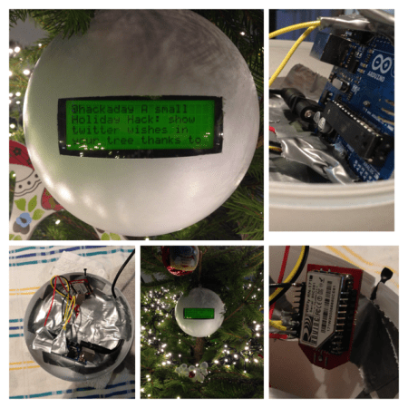
The holidays are long over, but we’re still getting a smattering of holiday themed hacks. For this one, the [Han’s] family decided to make a Christmas bauble that relays their tweets to them!

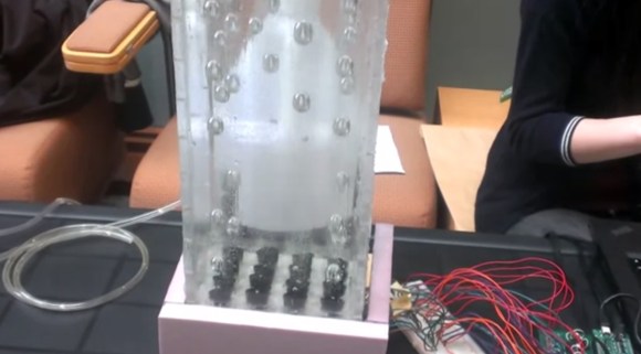
They call it the Tweetbal which is Dutch for — well — Tweetball! Whenever someone tweets with the hashtag #tweetbal it gets displayed on the 20×4 serial LCD display. They’re using an Arduino Uno with an RN-XV WiFly module to receive and send the tweets to the display. A large white plastic ornament ball houses it all secured very firmly with our favorite adhesion method — duct tape. It’s a pretty simple project, but a great holiday hack if we do say so ourselves — plus it could be easily used for non-holiday purposes — like a desktop trinket twitter feed!

Stick around after the break to see its tweeting capabilities in action.

Continue reading “Christmas Tweetball”

Arduino Ball Throwing Game

arduinogame01_07

Building your own gaming platform is pretty cool on its own, but when the game actually looks like fun to play, well that’s on a different level of cool. [Zippy314] designed an Arduino based game platform as a Christmas present to his son called the Das Blinken Bonken!

Like all highly addicting games, the gameplay is simple; the player throws a ball at the target board while aiming to hit a specific ‘pad’. As shown in the video after the break, there are many game possibilities with this platform, like trying to hit the illuminated target each time, or just trying to hit all of the pads on the board as fast as possible.

A pad is registered as a ‘hit’ with the help of home-made pressure sensors, which are each constructed in a ‘sandwich’ of pressure-sensitive conductive sheets. This is the same material used in these LED Sneakers. Since the resistance through the sheet lowers as pressure is applied, a simple voltage divider circuit is used to feed the analog inputs on the Arduino, thus making it very easy to detect a ‘hit’. An I2C 4-Digit 7 Segment display keeps score and displays the game title, while a strip of addressable RGB LEDs give player feedback and other vital gameplay information.

Continue reading “Arduino Ball Throwing Game”

3D Bubble Display

3dbubbledisplay

[Craig Shultz], a mechatronics grad student at Northwestern University, sent us a video of his group’s project from last winter: a 3D bubble display. We’ve seen some pretty impressive and innovative bubble displays around here—most recently the 60-tube RGB LED build—but [Craig’s] is the first we’ve seen that adds some depth to the project.

For the most part, its construction is what you’d expect: an acrylic case enclosing the 4×4 arrangement of tubes, 16 valves 16 individually controlled solenoids, and some small air pumps; all driven by a PIC microcontroller. In the video, however, you’ll have to strain your eyes if you want to see the tubes, which is a clever design choice on [Craig’s] part to showcase the display’s depth. Each of the bubbles was visually separated by pairing glycerin with a tubing material that had a similar index of refraction, Pyrex. As a result, the tubes blend seamlessly into the fluid. Check out the video after the break.

Continue reading “3D Bubble Display”

A Simple (and Dirty) Bill Of Materials And Stock Management Utility

As many readers may already know, when I’m not featuring your projects or working on the mooltipass I try to make simple things that may be useful to electronics enthusiasts. My latest creation is a simple bill of materials generation tool, which can also do simple stock management. Unfortunately for Linux users, this utility is made using Visual Basic functions in an Excel file.

It works fairly simply: just enter your schematics’ components references in the excel sheet, along with the corresponding Digikey webpage address. Click on the “fetch” button and the script will automatically get all your component characteristics from the internet and tell you the component costs depending on the number of prototypes you want to make. Then click the “sort BoM” button and your BoM will automatically be sorted by component type and value. Another functionality allows you to check that all the components present in your BoM are also present on the (very simple) Kicad generated one. Finally, using another Excel sheet containing your current stock, the Bill of Materials will let you know if you have enough components for the assembly stage. A video of the tool in action is embedded after the break, and you can download the BoM template here (.XLSM file) and the corresponding stock file there (.XLSM file).

Continue reading “A Simple (and Dirty) Bill Of Materials And Stock Management Utility”

Self-Balancing Robots Wobble, But They Don’t Fall Down

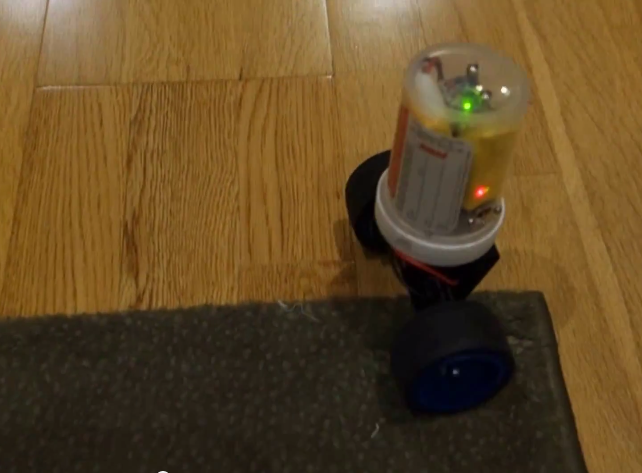
[Trandi] can check ‘build a self-balancing robot’ off of his to-do list. Over a couple of weekends, he built said robot, and, in his own words, managed not to over-design it. It even kept the attention of his 2-year-old son for several minutes, and that’s always a plus.

He was originally going to re-purpose one of his son’s RC cars, but didn’t want to risk breaking it. Instead, he designed a triangular 3-D printed chassis to hold a motor and some cogs to fit both the motor shaft and some re-used Meccano wheels. [Trandi]’s design employs an MPU 6050 6-DOF IMU for the balancing act and is built on an Arduino Nano clone.

[Trandi] is controlling the motor with an L293D, which has built-in flyback diodes to minimize spikes. He found that the Nano clone was not powerful enough to handle everything, so he added an L7805CV voltage regulator. After the break, watch [Trandi]’s cute bot tool around on various types of terrain, with and without a payload.

Don’t have an IMU lying around? You don’t really need one to build a self-balancing bot, as this IR-based lilliputian bot will demonstrate.

Continue reading “Self-Balancing Robots Wobble, But They Don’t Fall Down”

Fail Of The Week: Frying FETs With 500mA

fotw-mosfet-smoke-at-500ma

When [Simon] fried his 3A rated FET with just 500mA of current he wrote it off to an inability of the SOT23 package to dissipate the heat without a heatsink. For the next iteration of the project he upgraded to a 12A rated part. Luckily he decided to test the circuit one more time before sending his board off for fab. He threw together this constant current load test which led him to discover his failure.

The switching circuit, which was for his home security system project that we’ve seen at least twice, worked just fine up to 500mA. But when he drove it above that threshold the package quickly warmed up. It got so hot that it actually reflowed its solder joints! The problem has to do with oscillation, but even with further testing he couldn’t get the FET to reliably shut off all the way. Take a look at his fail write-up linked at the top and then let us know some possible remedies for the situation.


2013-09-05-Hackaday-Fail-tips-tileFail of the Week is a Hackaday column which runs every Wednesday. Help keep the fun rolling by writing about your past failures and sending us a link to the story — or sending in links to fail write ups you find in your Internet travels.

Designing, Simulating And Testing A Simple Radio Duty-Cycling Protocol For Contiki

A few days ago we featured [Marcus]’ Contiki port to the TI Launchpad, Contiki being an open source operating system dedicated to the Internet of Things created by [Adam Dunkels] at the SICS in Sweden. Part of [Marcus]’ work involved designing a simple radio duty-cycling protocol that achieves 3% idle listening duty cycle while allowing for an average 65ms latency with no prior contact or synchronization.

As a few readers may already know, it takes quite a lot of power for a wireless device to listen/send data. A platform therefore needs to have an algorithm that minimizes power consumption while allowing a (regular) planned data transfer. After creating his protocol named SimpleRDC, [Marcus] first simulated it using the Cooja simulator in order to check that it could perform as desired. He then implemented a real life test and checked the protocol’s performance by sniffing the SPI lines connecting his MSP430 to the wireless module and by monitoring the platform power consumption with his oscilloscope and a shunt resistor.