AppCAD Does Transmission Lines

Broadcom and Agilent are perhaps not household words in every household, but among those who work with RF, they are common enough names. An Agilent developer wrote AppCAD to help with common RF design computations and now works for Avago who bought Broadcom. But whoever’s branding is on it, you can download the tool from Broadcom or check out the latest beta version. Then watch [IMASI Guy’s] video below on how to use part of it.

What can it do? According to the website:

  • S-Parameter Analysis and Plotting
  • Active Circuit Bias Design
  • Cascade Noise and IP3 Analysis
  • Transmission Line Analysis
  • Signals and Systems
  • Complex Math Engineering Calculator

Continue reading “AppCAD Does Transmission Lines”

Avago Buys Broadcom For $37 Billion

The economy is doing well, and that means companies are spending money. Companies in the chip business are in fact businesses, and spending money to them means acquisitions and mergers. The latest such deal is Avago Technologies buying Broadcom for $37 Billion USD – the largest deal ever made in the semiconductor industry.

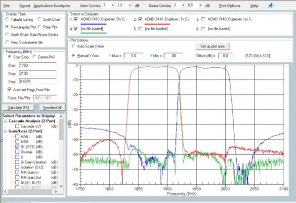
The products made by these two companies aren’t usually found in stock at Adafruit, Sparkfun, or in the BOMs on Hackaday.io, but that doesn’t mean these chips aren’t extremely popular in the industry. Avago has a huge catalog of RF goodies and a surprising number of LED products. Broadcom, outside of the SoC found in the Raspberry Pi, likewise isn’t seen very often on workbenches, but their chips are found in everything from set-top boxes to Ethernet and broadband equipment.

Just a few months ago, a merger between NXP and Freescale struck a little bit closer to our hearts, but there is an opportunity for this acquisition to be much more interesting. The company that emerges from the NXP and Freescale merger will be saddled with hundreds of chip lines that all compete with each other – a cornucopia of ARMs, 8051s, Kinetis,  iMX.6, and ColdFires, and that’s just microcontrollers. Avago and Broadcom don’t have a catalog that overlaps nearly as much, and it will be very interesting to see what they can come up with.

Fail Of The Week: Color Meter For Adjusting LEDs

fotw-color-meter

[John Peterson] answered our call to document your hacks by discussing what he learned while building this color meter. He conceived the project as a way to precisely match the color output of LEDs driven with a PWM signal. The thought was that it could sample an LED’s output, then use that data to calculate values necessary to match the color of other LEDs. This is a good idea when using LEDs of different types, but even diodes from the same production line can show variations in color output.

Of course this project wouldn’t be featured as a Fail of the Week if it worked as he had expected. It turns out the sensor that he used, an Avago ADJD-S371-QR999 on a SparkFun breakout board, takes very quick color readings. This is great for solid objects, but not great for a light source being switched on and off like the PWM LEDs.

We like it that [John] posted a list of lesson learned on the project. The real fail is in trying to use this particular sensor, but we figure there must be some way to get meaningful data through sampling. Check out the page for the retired sensor which also includes a link to the datasheet. Can you think of a firmware hack which would allow this hardware to sample so that the PWM value could be extrapolated through averaging or other calculations? Let us know in the comments.


2013-09-05-Hackaday-Fail-tips-tileFail of the Week is a Hackaday column which runs every Wednesday. Help keep the fun rolling by writing about your past failures and sending us a link to the story — or sending in links to fail write ups you find in your Internet travels.

Adding An Optical Mouse Sensor To An Autonomous Vehicle

[Tim] is getting his drone ready for SparkFun’s 2013 Autonomous Vehicle Competition on June 8th. He has a pretty good start, but was having some problems accurately measuring travel distance. The technique he chose for the task was to glue magnets onto the axles of the vehicle and monitor them with a hall effect sensor. Those sensors are finicky and a few problems during testing prompted him to look at a redundant system. Right now he’s experimenting with adding an optical mouse sensor to the autonomous vehicle.

Recently we saw the same concept used, but it was meant for tracking movement of a full-sized automobile. If it can work in that application it should be perfect here since the vehicle is much closer to the ground and will be used in ideal conditions (flat pavement with clear weather). [Tim] cracked open an old HP mouse he had lying around. Inside he found an Avago ADNS-5020 sensor. After grabbing the datasheet he discovered that it’s simply an I2C device. Above you can see the Arduino Leonardo he used for the first tests.

[Tim] coded functions to monitor the chip, including some interesting ones like measuring how in-focus the surface below the sensor is. This brings up a question, is there limit on how fast the vehicle can travel before the sensor fails to report back accurately?