Android Based Wireless ECG

ECG

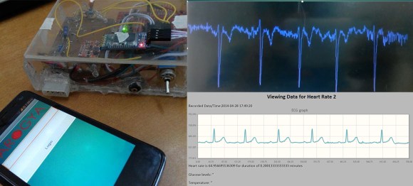
The title of [Nuclearrambo’s] post says it all, “Android based wireless ECG monitoring (Temperature sensor and glucometer included).” Wow! What a project!

The project is built around the HC-06 bluetooth module and the Stellaris LaunchPad from TI, an inexpensive ARM developer kit. Building an ECG is a great way to learn about instrumentation amplifiers, a type of differential amplifier used for its extremely high common mode rejection ratio (CMRR). Please be sure to keep in mind that there are a myriad of safety issues and regulation concerns for medical device, and there is no doubt that an ECG is considered a medical device. Sadly, [Nuclearrambo’s] post does not include all of the code and design files you need to build the system, which is understandable considering this is a medical device. That being said, he provides a lot of information about building high-quality ECG instrumentation and the web interface.

It would be great if [Nuclearrambo] could post the Android application code and Stellaris LaunchPad code. Even with these omissions, this post is still worth reading. Designing medical devices requires a lot of know-how, but who knows, maybe your next project can save your life!

MobilECG Goes Open Source

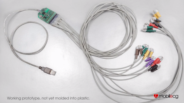
After a failed crowdfunding campaign, MobilECG has gone open source. MobilECG is a medical grade 12 lead electrocardiograph. A 12 lead system is quite a bit more complex than some of the ECG systems we have featured in the past.  [Péter], the founder and designer of the device attempted to fund it through an Indiegogo campaign. While MobilECG is relatively cheap, medical certifications are not. The campaign didn’t reach its goal of $230,000 USD. [Péter] tried again with a grass-roots donation round at his website. That round also fell short of [Péter’s] goal to keep working on the project. Rather than let his hard work go to waste, [Péter] has made the decision to release his hardware and software to the community. The hardware is licensed under CERN OHL v1.2. The software is released under the humorously named WTFPL.

While we’re not ECG experts, the basic hardware design appears to be sound. MobileECG is based around the Texas Instruments ADS1278 octal analog to digital converter. Two AVR microcontrollers are used, an ATTiny24, and an ATUC64. The analog design incorporates such niceties as lead off detection and defibrillator protection. It should be noted that there are some known bugs in the design, [Péter] mentions he can be contacted with questions. The software seems to be in an early state, and would require quite a bit of work to get it to a final design. While we do wish [Péter] had better luck with his campaign, we’re always glad to see designs released into the open source community.

Continue reading “MobilECG Goes Open Source”

Arduino Powered ECG Informs Users Of Their Death

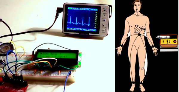
Just when you thought you’d seen an Arduino do everything, [birdyberth] built an Arduino powered Electrocardiogram (ECG or EKG). Electrocardiography is a non invasive method of studying the heart. For many of us that means a 10 minute test during our yearly physical exam. Medical grade ECGs can use up to 10 electrodes. To keep things simple [birdyberth] went the route of a few circuits we’ve seen before, and reduced it to two electrodes and a ground reference. [birdyberth] makes note that the circuit is only safe if battery power is used.

The “heart” of any ECG is an instrumentation amplifier. Instrumentation amplifiers can be thought of as super differential amplifiers. They have buffered inputs, low DC offset, low drift, low noise, high open loop gain, and high impedance among other favorable characteristics. The downside is cost. A typical op amp might cost 0.50 USD in single piece quantities. Instrumentation amplifiers, like [birdyberth’s] INA128 can cost $8.30 or (much) more each. The extra cost is understandable when one thinks about the signals being measured. The ECG is “picking up” the heart’s electrical signals from the outside on skin. On commonly used ECG graph paper, a 1mm square translates to about .1 mV. High gain and clean signals are really needed to get any meaningful data here.

Electrodes are another important part of an ECG. Medical grade ECG units typically use disposable adhesive electrodes that make a strong electrical connection to the skin, and hurt like heck when they’re ripped off by the nurse. [birdyberth] was able to make electrodes using nothing more than tin foil and paper clips. We think the real trick is in the shower gel he used to make an electrical connection to his skin. While messy, the gel provides a low resistance path for the tiny currents to flow.

The actual processing in [birdyberth’s] circuit is easy to follow. The signal from the instrumentation amplifier is sent through a low pass filter, through a 741 op amp, and then on to the Arduino. The Arduino uses a 16×2 LCD to display heart rate in beats per minute, along with a friendly message informing you if you are alive or dead. The circuit even provides audible feedback for heart beats, and the classic “flatline tone” when the users either disconnects the electrodes or expires. [birdyberth] has also plugged in his pocket oscilloscope just after the low pass filter. As his video shows, the familiar ECG waveform is clearly visible. We’d love to see a more complex version of this hack combined with [Addie’s] heart simulator, so we could know exactly which heart malady is killing us in real time!

Continue reading “Arduino Powered ECG Informs Users Of Their Death”

A Handful Of Parts Used To Form An Electrocardiogram

minimal-ecg

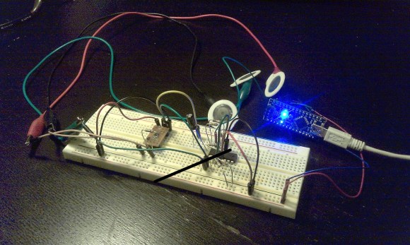
It’s difficult to image a more bare-bones approach to building an ECG. [Raul] used an Arduino nano to collect samples and push them to a computer for graphing.

An Electrocardiogram measures electrical activity around your heart. The white circles above are the sensors which he picked up in a box of fifty for 11 Euros (under $15). Stick them on your skin in just the right places and they’ll report back on what your heart is doing.

He used a AD8221 to amplify the signals. He mentions that this is an ins-amp, not an op-amp. We didn’t find a concise reference explaining what that is. It might be a good topic for the comments section. The signal from that chip feeds into an LM324 op-amp before being dumped into the Arduino.

Simplicity comes at a price. This measures very small electrical impulses and has very little in the way of shielding and filtering. Because of this you may need to do a rain dance, say a prayer, burn a candle, and stick needles into a doll to get a reliable signal on the other end.

Here’s another version that doesn’t require special sensors.

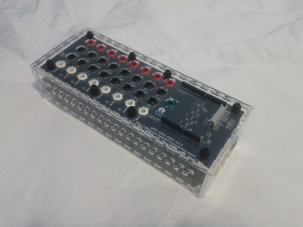
Fitting A Cold, Metal Heart In An Altoids Tin

sim

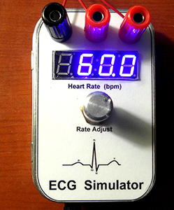
[James] has been building a heart rate monitor using a very cool TI chip. He needed a way to test his device, and commercial ECG simulators, like all biotech devices, are absurdly expensive. [James] decided to build his own heart rate simulator, and in the process made a great tool and one of the most well documented projects we’ve ever seen.

Of course, if you’re building an ECG simulator, you’re going to need a good sample of a heart’s electrical pattern. To get this sample, [James] found an old army manual with a diagram of an ideal ECG pattern. [James] took this PDF manual, screen capped the diagram, and used a Python script to generate an array in C the Arduino could repeat over and over.

The rest of the build consisted of a D/A converter, a pot to change the heart rate, a very nice seven-segment display, and a few banana jacks to connect to [James]’ heart monitor. Everything is up in a git, including an amazingly well documented (87 pages!) tutorial for building your own Arduino heart simulator.

DIY Propeller-based ECG

propeller_ecg

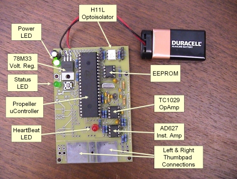
[Ray] likes to build all sorts of Propeller-based projects, but one of the more interesting items we came across was this DIY ECG. While we have covered other DIY electrocardiograms before, he left the breadboard behind and put together a nicely done PCB for his build.

The ECGs design should be pretty familiar to anyone that has seen our ECG coverage in the past. The user places his thumbs on the large built-in pads, which allow the circuit to sense the electrical signals produced by heart’s contractions. These small electrical impulses are then amplified using an AD627 instrument amplifier before being further amplified via a dual op-amp.

The amplified signal is filtered and then fed into the Propeller’s ADC, which displays the user’s heart rhythms via an LED. The data can also be fed into a computer via an optoisolated serial connection.

[Ray] lays out a litany of warnings and precautions that should be followed before downloading his schematics and firmware. We have to echo those warnings, as it doesn’t take a large well-placed shock to disrupt the heart.

Wireless Electrocardiography… With IPhone

This module is a sensor package for monitoring the electrical activity of the heart. It is the product of an effort to create a Wireless Body Sensor Network node that is dependable while consuming very little electricity, which means a longer battery life. To accomplish this, the microcontroller in charge of the node compresses the data (not usually done with wireless ECG hardware) so that the radio transmissions are as short and infrequent as possible.

[Igor] sent us this tip and had a short question and answer session with one of the developers. It seems they are working with the MSP430 chips right now because of their low power consumption. Unfortunately those chips still draw a high load when transmitting so future revisions will utilize an alternative.

Oh, and why the iPhone? The device that displays the data makes little difference. In this case they’re transmitting via Bluetooth for a real-time display (seen in the video after the break). This could be used for a wide variety of devices, or monitored remotely via the Internet.

Continue reading “Wireless Electrocardiography… With IPhone”