Transistor Logic Clock Gets Stacked Up

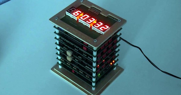
A couple years back we covered a very impressive transistor logic clock which was laid out so an observer could watch all of the counters doing their thing, complete with gratuitous blinkenlights. It had 777 transistors on 41 perfboards, and exactly zero crystals: the clock signal was extracted from the mains frequency of 50 Hz. It was obviously a labor of love and certainly looked impressive, but it wasn’t exactly the most practical timepiece we’d ever seen.
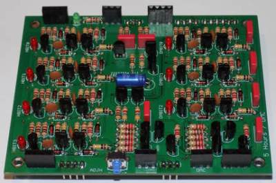
Creator [B Brett] recently wrote in to share news that the second version of his transistor logic clock has been completed, and we can confidently say it’s a triumph. He’s dropped the 41 perfboards in favor of 9 professionally fabricated PCBs, which this time around are stacked vertically to make it a bit more desktop friendly. The end goal of a transistor logic clock that you can take apart to study is the same, but this “MkII” as he calls it is a far more refined version of the concept.

In addition to using fewer boards, the new MkII design cuts the logic down to only 283 transistors. This is thanks in part to the fact that he allowed himself the luxury of including an oscillator this time. The clock uses a standard watch crystal at 32.768 KHz, the output of which is converted into a square wave through a Schmitt trigger. This is then fed into a divider higher up the stack which uses flip flops to produce 1Hz and 2Hz signals for use throughout the rest of the clock.

In addition to the original version of this project, we’ve also seen a beautiful single-board wall mounted version, and even a “dead bug” style one built from scraps.

Continue reading “Transistor Logic Clock Gets Stacked Up”

Learn Flip Flops With (More) Simulation

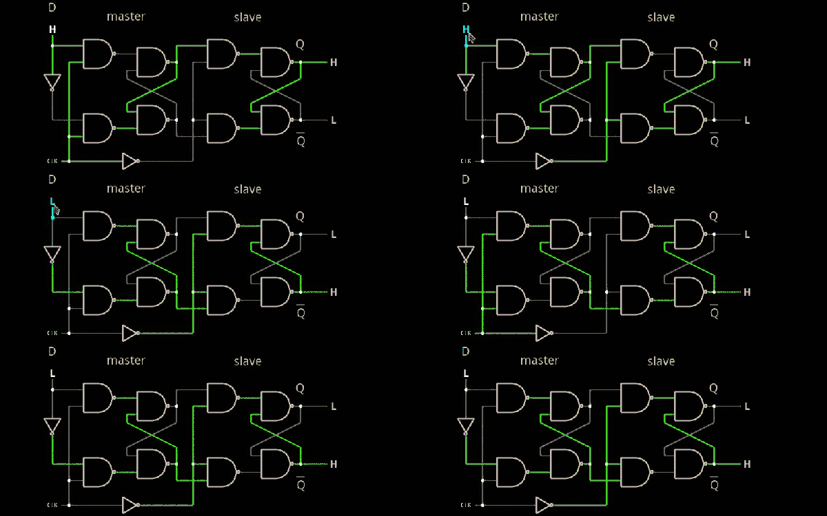
In the previous installment, we talked about why flip flops are such an important part of digital design. We also looked at some latch circuits. This time, I want to look at some actual flip flops–that is circuit elements that hold their state based on some clock signal.

Just like last time, I want to look at sequential building blocks in three different ways: at the abstraction level, at the gate level, and then using Verilog and two online tools that you can also use to simulate the circuits. Remember the SR latch? It takes two inputs, one to set the Q output and the other to reset it. This unassuming building block is at the heart of many other logic circuits.

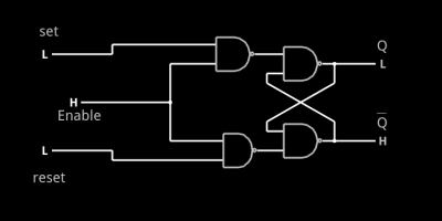
circ5A common enhancement to the SR latch is to include an enable signal. This precludes the output from changing when the enable signal is not asserted. The implementation is simple. You only need to put an additional gate on each input so that the output of the gate can’t assert unless the other input (the enable) is asserted. The schematic appears on the right.

In the case of this simulation (or the Verilog equivalent), the SR inputs become active high because of the inversion in the input NAND gates. If the enable input is low, nothing will change. If it is high, then asserted inputs on the S or R inputs will cause the latch to set or reset. Don’t set both high at the same time when the enable is high (or, go ahead–it is a simulation, so you can’t burn anything up).(Note: If you can’t see the entire circuit or you see nothing in the circuit simulator, try selecting Edit | Centre Circuit from the main menu.)

Continue reading “Learn Flip Flops With (More) Simulation”

Learn Flip Flops With Simulation

Digital design with combinatorial gates like AND, OR, and NOT gates is relatively straightforward. In particular, when you use these gates to form combinatorial logic, the outputs only depend on the inputs. The previous state of the outputs isn’t important in combinatorial logic. While this is simple, it also prevents you from building things like state machines, counters, and even CPUs.

Circuits that use their own outputs as inputs are known as sequential circuits. It is true that at the fundamental level, sequential circuits use conventional logic gates. However, you usually won’t deal with them as gates, but will deal with abstractions like latches, flip flops, and even higher level constructs. Learning about these higher level constructs will allow you to make more advanced digital designs that are robust. In fact, if you are using an FPGA, building blocks like flip flops are essential since a large portion of the chip will be made up of some kind of flip flop.

Continue reading “Learn Flip Flops With Simulation”