An overlay is shown on a topographical map. High points are highlighted in blue. The letters "A" and "B" are shown in red text at two points.

Using A Scientific Satellite For Passive Radar

The basic principle of radar systems is simple enough: send a radio signal out, and measure the time it takes for a reflection to return. Given the abundant sources of RF signals – television signals, radio stations, cellular carriers, even Wi-Fi – that surround most of us, it’s not even necessary to transmit your own signal. This is the premise of passive radar, which uses passive RF illumination to form an image. The RF signal doesn’t even need to come from a terrestrial source, as [Jean Michel Friedt] demonstrated with a passive radar illuminated by the NISAR radar-imaging satellite (pre-print paper).

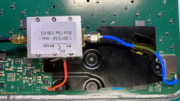
NISAR is a synthetic-aperture radar satellite jointly built by NASA and ISRO, and it completes a pass over the world every twelve days. It uses an L-band chirp radar signal, which can be picked up with GNSS antennas. One antenna points up towards the satellite, and has a ground plane blocking the signal from directly reaching the second antenna, which picks up reflections from the landscape under observation. Since the satellite would illuminate the scene for less than a minute, [Jean-Michel] had to predict the moment of peak intensity, and achieved an accuracy of about three seconds.

The signals themselves were recorded with an SDR and a Raspberry Pi. High-end, high-resolution SDRs such as the Ettus B210 gave the best results, but an inexpensive homebuilt MAX2771-based SDR also produced recognizable images. This setup won’t be providing any particularly detailed images, but it did accurately show the contours of the local geography – quite a good result for such a simple setup.

If you’re more interested in tracking aircraft than surveying landscapes, check out this ADS-B-synchronized passive radar system. Although passive radar doesn’t require a transmitter license, that doesn’t mean it’s free from legal issues, as the KrakenSDR team can testify.

PCB of the antenna about to be modded, with components desoldered and different parts of the circuit highlighted

Make A GPS Antenna Compatible With Same Manufacturer’s Receiver

GPS can be a bit complex of a technology – you have to receive a signal below the noise floor, do quite a bit of math that relies on the theory of relativity, and, adding insult to injury, you also have to go outside to test it. Have you ever wondered how GPS antennas work? In particular, how do active GPS antennas get power down the same wire that they use to send signal to the receiver? Wonder not, because [Tom Verbeure] gifts us a post detailing a mod letting a fancy active GPS antenna use a higher-than-expected input voltage.

[Tom]’s post has the perfect amount of detail – enough pictures to illustrate the entire journey, and explanations to go with all of it. The specific task is modifying a Symmetricom antenna to work with a Symmetricom GPS receiver, which has a puzzling attribute of supplying 12V to the antenna instead of more common 3.3V or 5V. There’s a few possible options detailed, and [Tom] goes for the cleanest possible one – replacing the voltage regulator used inside of the antenna.

With a suitable replacement regulator installed and a protection diode replaced, the antenna no longer registers as a short circuit, and gets [Tom] a fix – you, in turn, get a stellar primer on how exactly active GPS antennas work. If your device isn’t ready to use active GPS antennas, [Tom]’s post will help you understand another GPS antenna hack we covered recently – modifying the Starlink dish to use an active antenna to avoid jamming on the frontlines.

A bias tee module added inside the Starlink terminal, connected to the pads where a GPS antenna used to be wired

GPS Antenna Mods Make Starlink Terminal Immune To Jammers

The Starlink receivers need positioning and precise timing information to function, and currently the best way to get that information is to use a global navigation satellite system (GNSS) such as GPS. Unfortunately, the antenna used for this secondary satellite connection leaves something to be desired. Of course, when it comes to solving Starlink problems, there’s no one best than [Oleg Kutkov], whose duty is to fix and improve upon Starlink terminals used in Ukraine — and when the specific problem is GPS bands getting jammed by the invading military, you better believe that a fix is due.

[Oleg] sets the scene, walking us through the evolution of GPS circuitry on the Starlink terminals. Then he shows us the simplest mods you can do, like soldering an improved passive antenna in place of the chip antenna currently being used. Then, he takes it up a notch, and shows us how you could attach an active antenna by using a bias tee module, a mod that would surely work wonders on more than just this device! Then, he brings out the test result tables — and the differences are impressive, in that the Starlink terminals with active antenna mods were able to get GPS signal in areas with active jamming going on, while the unmodified ones could not.

The post is exceptionally accessible, and a must read for anyone wondering about GPS antenna reception problems in customer-accessible devices. This is not the only Starlink hardware mod we’ve seen [Oleg] make, we’ve just covered his Starlink Ethernet port restoration journey that meticulously fixes Ethernet connectivity oversights in the newer models, and the blog also has an article about powering Starlink terminals without the need for PoE, so, do check it out if you’re looking for more!