A Homebrew Gas Chromatograph That Won’t Bust Your Budget

Chances are good that most of us will go through life without ever having to perform gas chromatography, and if we do have the occasion to do so, it’ll likely be on a professional basis using a somewhat expensive commercial instrument. That doesn’t mean you can’t roll your own gas chromatograph, though, and if you make a few compromises, it’s not even all that expensive.

At its heart, gas chromatography is pretty simple; it’s just selectively retarding the movement of a gas phase using a solid matrix and measuring the physical or chemical properties of the separated components of the gas as they pass through the system. That’s exactly what [Markus Bindhammer] has accomplished here, in about the simplest way possible. Gas chromatographs generally use a carrier gas such as helium to move the sample through the system. However, since that’s expensive stuff, [Markus] decided to use room air as the carrier.

The column itself is just a meter or so of silicone tubing packed with chromatography-grade silica gel, which is probably the most expensive thing on the BOM. It also includes an injection port homebrewed from brass compression fittings and some machined acrylic blocks. Those hold the detectors, an MQ-2 gas sensor module, and a thermal conductivity sensor fashioned from the filament of a grain-of-wheat incandescent lamp. To read the sensors and control the air pump, [Markus] employs an Arduino Uno, which unfortunately doesn’t have great resolution on its analog-to-digital converter. To fix that, he used the ubiquitous HX7111 load cell amplifier to read the output from the thermal conductivity sensor.

After purging the column and warming up the sensors, [Markus] injected a sample of lighter fuel and exported the data to Excel. The MQ-2 clearly shows two fractions coming off the column, which makes sense for the mix of propane and butane in the lighter fuel. You can also see two peaks in the thermal conductivity data from a different fuel containing only butane, corresponding to the two different isomers of the four-carbon alkane.

[Markus] has been on a bit of a tear lately; just last week, we featured his photochromic memristor and, before that, his all-in-one electrochemistry lab.

Continue reading “A Homebrew Gas Chromatograph That Won’t Bust Your Budget”

[Ben Krasnow] Looks Inside Film Camera Date Stamping

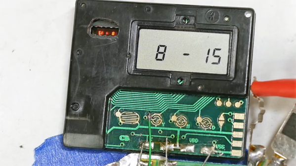
Honestly, we never wondered how those old film cameras used to put the date stamp in the lower right-hand corner of the frame. Luckily, [Ben Krasnow] does not suffer from this deplorable lack of curiosity, and his video teardown of a date-stamping film camera back (embedded below) not only answers the question, but provides a useful lesson in value engineering.

For the likely fair fraction of the audience who has never taken a photo on film before, cheap 35-mm cameras were once a big thing. They were really all one had for family snapshots and the like unless you wanted to invest in single-lens reflex cameras and all the lenses and accessories. They were miles better than earlier cartridge cameras like the 110 or – shudder – Disc film, and the cameras started getting some neat electronic features too. One was the little red-orange date stamp, which from the color we – and [Ben] assumed was some sort of LED pressed up against the film, but it ends up being much cooler than that.

Digging into the back of an old camera, [Ben] found that there’s actually a tiny projector that uses a mirror to fold the optical path between the film and a grain-of-wheat incandescent bulb. An LCD filter sits in the optical path, but because it’s not exactly on the plane of the film, it actually has to project the image onto the film. The incandescent bulb acts as a point source and the mirror makes the optical path long enough that the date stamp image appears sharp on the film. It’s cheap, readily adapted to other cameras, and reliable.

Teardowns like this aren’t fodder for [Ben]’s usual video fare, which tends more toward homemade CT scanners and Apollo-grade electroluminescent displays, but this was informative and interesting, too.

Continue reading “[Ben Krasnow] Looks Inside Film Camera Date Stamping”

Tiny Light Bulb Flasher Vies For World’s Record

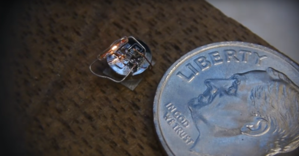
We’re going to go out on a limb here and declare this minuscule incandescent light flasher the smallest such circuit in the world. After all, when you need a microscope to see it work, you’ve probably succeeded in making the world’s smallest something.

Even if it’s not record breaking, [Ben Krasnow]’s diminutive entry in the 2017 Flashing Light Contest, which we recently covered, is still pretty keen. For those not familiar with the contest, it’s an informal challenge to build something that electrically switches an incandescent light on and off in the most interesting way possible for the chance to win £200. [Ben] says he’ll donate the prize money to a STEM charity if he wins, and we’d say he has a good chance with this flea-sized entry.

The incandescent lamp he chose is a specialty item for model makers and scale railroad enthusiasts; we’d heard of “grain of wheat” bulbs before, but this thing is ridiculous. The bulb makes the 4.6 mm diameter SR416 hearing aid battery that powers the flasher look enormous. The driver is a clever Schmitt trigger inverter with a tiny RC network to flash the bulb at about 1 Hz. The video below shows the flasher working and details the development and the build, which featured spot welding to the battery. [Ben] has even spec’d precisely how many Joules of energy will rupture the thing steel cases on these cells — we suspect involuntarily through trial and error.

[Ben]’s entry in the contest is now our favorite, and not just because he’s been a great friend to Hackaday with such classic hacks as watching a phonograph needle with an electron microscope and a homebrew CT scanner. This circuit is genuinely fascinating, and we hope it inspires you to try to top it. There’s a little less than a month left in the contest, so get to it.

Continue reading “Tiny Light Bulb Flasher Vies For World’s Record”