Got Fireflies? Try Talking To Them With A Green LED

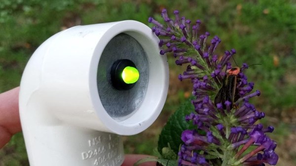
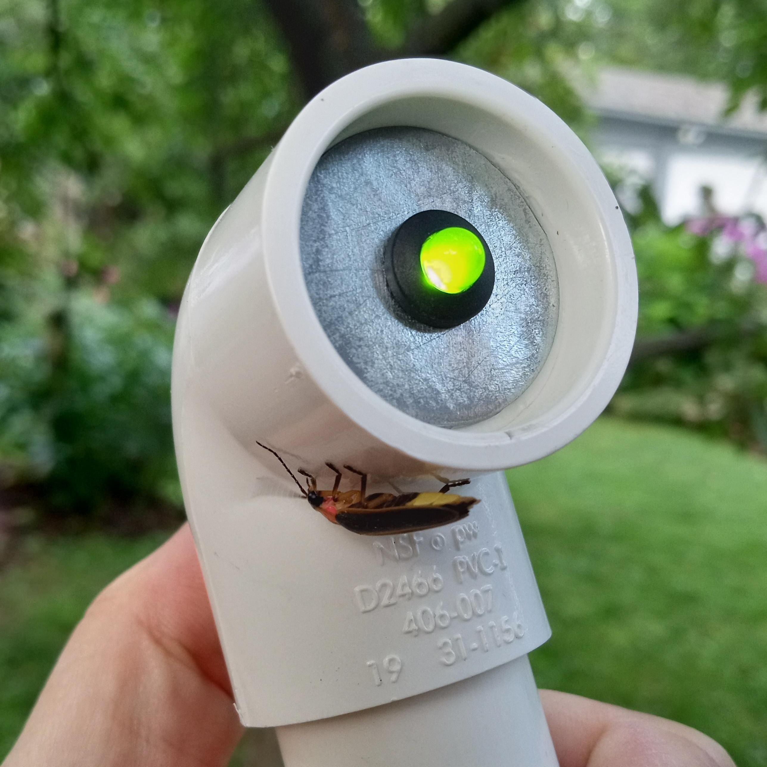
[ChrisMentrek] shares a design for a simple green LED signal light intended for experiments in “talking” to fireflies. The device uses simple components like PVC piping and connectors to make something that resembles a signal flashlight with a momentary switch — a device simple enough to make in time for a little weekend experimenting.

Observe and repeat flashing patterns, and see if any fireflies get curious enough to investigate.

Did you know that fireflies, a type of beetle whose lower abdomen can light up thanks to a chemical reaction, flash in patterns? Many creatures, fireflies included, are quite curious under the right circumstances. The idea is to observe some fireflies and attempt to flash the same patterns (or different ones!) with a green LED to see if any come and investigate.

[ChrisMentrek] recommends using a green LED that outputs 565 nm, because that is very close to the colors emitted by most fireflies in North America. There’s also a handy link about firefly flashing patterns from the Massachusetts Audubon society’s Firefly Watch program, which is a great resource for budding scientists.

If staying up and learning more about nocturnal nightlife is your thing, then in between trying to talk to fireflies we recommend listening for bats as another fun activity, although it requires a bit more than just a green LED. Intrigued? Good news, because we can tell you all about the different kinds of bat detectors and what you can expect from them.

Test Your Capacity For Circuit Sculpture With Flashing Lights

Have you tried your hand at circuit sculpture yet? Well, if you were waiting for the ideal first project with a great build video to go along with it, keep reading. [4dcircuitry]’s 555-based flashing circuit sculpture ticks all the go-for-it boxen for us — the component list is short, the final circuit looks cool, and well, there are blinkenlights.

Of course, it’s not quite a zero-entry project. Although [4dcircuitry] makes it look oh-so easy build it in the video below, they are using 1206 components and an SOIC-packaged 555 timer here. On the other hand, they start by smartly laying everything out on double-stick tape before applying flux and soldering. Then when it’s time to run the wires that no one wants to see, [4dcircuitry] carefully tweezers it from the tape and flips it over, re-using the tape do solder up the back side.

Don’t have the patience to solder 1206? All component sizes are beautiful, as evidenced by this amazing circuit sculpture clock.

Continue reading “Test Your Capacity For Circuit Sculpture With Flashing Lights”

Flashing TI Chips With An ESP

Texas Instruments is best known to the general public for building obsolete calculators and selling them at extraordinary prices to students, but they also build some interesting (and reasonably-priced) microcontrollers as well. While not as ubiquitous as Atmel and the Arduino platform, they can still be found in plenty of consumer electronics and reprogrammed, and [Aaron] aka [atc1441] demonstrates how to modify them with an ESP32 as an intermediary.

Specifically, the TI chips in this build revolve around the 8051-core  microcontrollers, which [Aaron] has found in small e-paper price tags and other RF hardware. He’s using an ESP32 to reprogram the TI chips, and leveraging a web server on the ESP in order to be able to re-flash them over WiFi. Some of the e-paper displays have built-in header pins which makes connecting them to the ESP fairly easy, and once that’s out of the way [Aaron] also provides an entire software library for interacting with these microcontrollers through the browser interface.

Right now the project supports the CC2430, CC2510 and CC1110 variants, but [Aaron] plans to add support for more in the future. It’s a fairly comprehensive build, and much better than buying the proprietary TI programmer, so if you have some of these e-paper displays laying around the barrier to entry has been dramatically lowered. If you don’t have this specific type of display laying around, we’ve seen similar teardowns and repurposing of other e-paper devices in the past as well.

Continue reading “Flashing TI Chips With An ESP”

Behind The Scenes Of The 2019 Superconference Badge

If you count yourself among the several hundred of our closest friends that have joined us at Supplyframe HQ for the 2019 Hackaday Superconference, then by now you’ll have your hands on one of this year’s incredible FPGA badges. It should come as no surprise that an incredible amount of time and effort went into developing and manufacturing this exceptionally unique piece of hardware; the slick gadget in your hands today took nearly an entire year to develop, and work continued on it until very literally the last possible moment.

Badge designer Jeroen Domburg (aka Sprite_TM), Hackaday staff, and a team of dedicated volunteers were still putting the final touches on these ambitious devices less than 24 hours before they were distributed to the first wave of Superconference attendees. Naturally, that’s not exactly how things were supposed to go. But when you’ve got a group of people that want to push the envelope and build something truly incredible, convincing them to actually stop working can be a challenge in itself.

In fact, development of the badge is still ongoing. Fixes and improvements are being made to the software even as you read this, and if you haven’t already, you should upgrade your badge to make sure you’ve got the latest and greatest from our international team of wizards. We all know that conference badges have an unfortunate habit of languishing on the shelf and collecting dust, but the 2019 Superconference badge was built to challenge you for longer than just one weekend. Consider yourself warned: for every Supercon badge that gets tossed in a drawer come Monday, Sprite_TM will shed a single tear.

After the break, come along as we turn back the clock and take a look at the last minute dash to get 500+ badges programmed and ready to go before the doors opened for the 2019 Hackaday Superconference.

Continue reading “Behind The Scenes Of The 2019 Superconference Badge”

Tiny Light Bulb Flasher Vies For World’s Record

We’re going to go out on a limb here and declare this minuscule incandescent light flasher the smallest such circuit in the world. After all, when you need a microscope to see it work, you’ve probably succeeded in making the world’s smallest something.

Even if it’s not record breaking, [Ben Krasnow]’s diminutive entry in the 2017 Flashing Light Contest, which we recently covered, is still pretty keen. For those not familiar with the contest, it’s an informal challenge to build something that electrically switches an incandescent light on and off in the most interesting way possible for the chance to win £200. [Ben] says he’ll donate the prize money to a STEM charity if he wins, and we’d say he has a good chance with this flea-sized entry.

The incandescent lamp he chose is a specialty item for model makers and scale railroad enthusiasts; we’d heard of “grain of wheat” bulbs before, but this thing is ridiculous. The bulb makes the 4.6 mm diameter SR416 hearing aid battery that powers the flasher look enormous. The driver is a clever Schmitt trigger inverter with a tiny RC network to flash the bulb at about 1 Hz. The video below shows the flasher working and details the development and the build, which featured spot welding to the battery. [Ben] has even spec’d precisely how many Joules of energy will rupture the thing steel cases on these cells — we suspect involuntarily through trial and error.

[Ben]’s entry in the contest is now our favorite, and not just because he’s been a great friend to Hackaday with such classic hacks as watching a phonograph needle with an electron microscope and a homebrew CT scanner. This circuit is genuinely fascinating, and we hope it inspires you to try to top it. There’s a little less than a month left in the contest, so get to it.

Continue reading “Tiny Light Bulb Flasher Vies For World’s Record”

Faster Benchmarks With Slower Hardware

hardware

The Bus Pirate is a cheap, simple, Swiss army knife of electronic prototyping, capable of programming FPGAs, and writing to Flash memory. The uISP is possibly the most minimal way of programming Atmel chips over USB, using less than $5 in components. Although the uISP is using a slower chip and bit-banging the USB protocol, it turns out it’s actually faster when operating as a programmer for SPI Flash memories.

Most of [Necromancer]’s work involves flashing routers and the like, and he found the Bus Pirate was far too slow for his liking – he was spending the better part of four minutes to write a 2 MiB SPI Flash. Figuring he couldn’t do much worse, he wrote two firmwares for the uISP to put some data on a Flash chip, one a serial programmer, the other a much more optimized version.

Although the ATMega in the uISP is running at about half the speed as the PIC in the Bus Pirate, [Necromancer] found the optimized firmware takes nearly half the time to write to an 8 MiB Flash chip than the Bus Pirate.

It’s an impressive accomplishment, considering the Bus Pirate has a dedicated USB to serial chip, the uISP is bitbanging its USB connection, and the BP is running with a much faster clock. [Necro] thinks the problem with the Bus Pirate is the fact the bandwidth is capped to 115200 bps, or a maximum throughput of 14 kiB/s. Getting rid of this handicap and optimizing the delay loop makes the cheaper device faster.

Update: McHck’s Self Flashing Rig

A few weeks ago we featured the McHck project (pronounced McHack), a $5 Cortex M4 based platform which can be directly plugged into one’s computer. Recently, [Simon] announced that he made a firmware allowing a McHck to behave as a SWD adapter and also detailed his flashing rig.

Therefore, those who’d want to build their own McHck would only need to borrow an SWD programmer once to get started. When the first platform has been programmed with the SWD firmware, it can be used to flash and debug applications on the second McHck. Consequently, the microcontroller flashing rig [Simon] designed (shown in the picture above) is based on this. The few core elements are a TQFP48 ZIF programming socket, a push button and two LEDs. Simply push the Kinetis in the programming socket, close it and press the button. Success of the operation is indicated by the two LEDs. [Simon] used the Ragel State Machine Compiler to generate his flashing program and all the code he made can be downloaded from his github.

If you missed the original McHck post now’s your chance to go back and see what it is all about.