A Truly Professional Raspi Analog Input

Much to the chagrin of hardware tinkerers, the Raspberry Pi doesn’t have analog inputs on its GPIO pins. Sure, you can blink a LED with just a few console commands, but reading sensors with a bone-stock Raspi requires a little additional hardware. [Brian Dorey] just released a board that allows for 8 analog inputs on the Raspberry Pi with a 16-bit resolution that is much higher than any Arduino-based build.

[Brian]’s build is based on an earlier, similar iteration of a Raspi analog board we saw last July. Like the previous version, the new professionally made PCBs use a pair of Microchip MCP3428 analog to digital converter. These ADCs are able to sample four channels at a resolution of 16 bits; a vast improvement over the 8-bit ADCs included on every Arduino.

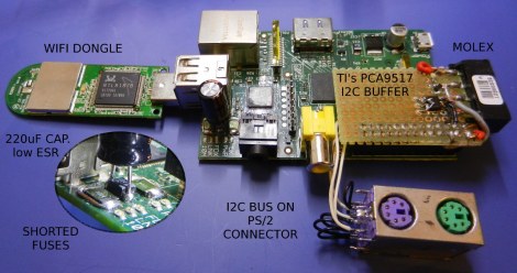
The boards communicate with the Raspberry Pi over an I2C serial bus using a neat stackable header. In theory, it should be possible to use several of these boards and measure dozens of analog channels, but we’ll leave a demonstration of that up to [Brian].

Word Clock Of A Different Nature

This work clock functions in an unexpected way. With each passing second it displays a random four letter word on the right side of the display. Traditional word clocks tell the time in natural language, but this one is simply used as a learning opportunity.

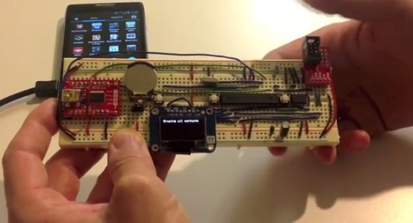
[Iron Jungle] got his hands on the display for just five buck from Deal Extreme. Looks like the price has gone up two dollars but that’s still a bargain. He wanted to use all eight digits of the display, and was looking for an opportunity to control more than one i2c device at a time. He ended up rolling an EEPROM and DS1307 RTC into the design. He figured the could display 24-hour time on four of the digits, and pull a library of four-letter words off of the EEPROM to fill the rest. He grabbed a word list off of the Internet then used a Python script to remove words containing 7-segment unfriendly characters (K, M, V, W, X, Z). The final touch was to use a salvaged relay to give the clock a ticking sound. Hear it for yourself in the clip after the break.

Continue reading “Word Clock Of A Different Nature”

An Adafruit Raspberry Pi Extravaganza

The folks at Adafruit are busy as a bee working on bringing some of their really cool boards to the Raspberry Pi platform. Here’s a few that came in over the last few days:

16 servos is almost too many

Servos require a PWM output but the Raspi only has hardware support for PWM on a single GPIO pin; certainly not enough to build a gigantic, city-leveling robot. [Kevin] over at Adafruit put together a tutorial for using this 16 channel servo driver with the Raspi.

12 bit DAC

With only one PWM pin and no analog out, it was only a matter of time before someone hooked up the Adafruit 12 bit DAC to the Raspberry Pi.

16×2 LCD displays

Both the servo and DAC builds use the Adafruit I2C library and a bit of Python. Of course it’s possible to treat the GPIO pins on the Raspberry Pi as digital outs, just as [Mikey] did with his Raspi LCD display tutorial.

So, what distro are you using?

Of course all these builds use Adafruit’s Occidentalis distro, a maker-friendly Linux distro we’ve posted about before. It’s too useful to languish as a single Hackaday post, so here it is again.

Raspberry Pi Keeps Tabs On Your Solar Power Setup

raspberrypi-solarlogger

[Brian Dorey] has been adding green power solutions to his home for some time now, and as things have progressed, he has experimented with several different iterations of data loggers. The latest system watching over his solar power setup is a Raspberry Pi armed with a custom-built I2C analog/digital converter.

The Rasp Pi is responsible for monitoring several different temperature sensors related to his solar water heating and storage system, but that’s just the beginning. It also keeps watch over his roof-mounted solar electric panels, his battery bank, and its charge controller. For good measure, he also monitors his home’s temperature and his water tank’s recirculation pump because, why the heck not?

All of the collected data is relayed to his web server where it is handsomely displayed for his perusal and analysis. [Brian] has made his code available here, so you can monitor your home in the same fashion with little fuss.

Start Thinking 4th Dimensionally With A Time Circuit Tutorial

When [Phil Burgess] showed off a few I2C – controlled seven-segment displays on adafruit’s weekly vlog, the comments immediately turned to the time circuits featured in everyone’s second-favorite time machine, the Back to the Future DeLorean. The time circuits are now active, so now you can easily add a temporal display to your car well before a hover conversion.

[Phil] used these LED displays, conveniently controlled by a four-wire I2C bus. Although the displays are addressable independently, it’s only possible to assign each display to one of 8 I2C addresses. [Phil] figured out a neat way to control the 9 displays of the time circuit with the help of a 74HC138 3-to-8 line decoder.

The case was constructed out of clear acrylic lasercut in adafruit’s shop and spray painted with faux-metal paint. After installing the seven-segment displays, a Teensy, ChronoDot, and a few AA batteries finished up the build.

With any luck, the design files for the laser cut case should be available shortly, so get those I2C displays while they’re still in stock.

Using Your Bench Tools To Test A New Display

It usually takes a bit of work to gain confidence when it comes to using new parts. [Glitch] got his hands on this OLED display which is manufactured by Sabernetics and wanted to give it a whirl before building a project around it. He grabbed his Bus Pirate to help learn the ins and outs of the new part.

The 96×16 Dot-Matrix display uses the i2c protocol, keeping the pin count really low (six pins for: ground, reset, clock, data, chip select, and voltage). Since the Bus Pirate gives you command-line-like access to i2c it’s a natural choice for a first test. In fact, the tool has been our go-to device for that protocol for most projects.

The first commands sent are configuration values for the SSD1306 that drives the display. These configure contrast, voltage conversion, and other important values necessary to power on the display. It sprung to life, showing random pixels since the RAM had not yet been initialized. With that success [Glitch] moved on to the Bus Pirate’s scripting capabilities and ended up with a Python script that drives the demo seen above. Now that he knows the commands he needs, it’ll be a lot easier to write code for a microcontroller driver.

Controlling Raspberry Pi Expansion Pins With A Web Interface

For the lucky few who have a Raspberry Pi board in their hands, you can now use the GPIO pins as a web interface (German, google translation). [Chris] is turning this magical board is turning a small device that can play 1080p video into something that can blink LEDs via the web.

The build started with an example of driving GPIO pins under Linux. [Chris] cobbled together a bit of PHP and Javascript on the Raspberry pi. Whenever he goes to the website hosted on the Pi, he’s greeted with the status and direction of a couple of expansion IO pins.

On a semi-related note, [Tony] is building a GPIO MIDI interface for his Pi. Yes, he could just get a USB to MIDI adapter and call it a day, but this is a far more professional looking solution to all the MIDI goodness the RasPi will deliver. If you’ve got any info on other RasPi breakout boards you’ve seen, send them in on the tip line.