Non Contact Scope Probe Costs Nearly Nothing

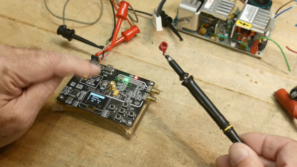
[IMSAI Guy] wants you to build a non-contact scope probe. The cost? Assuming you have a bit of wire and a regular scope probe, it won’t cost you anything. Why do you want such a thing? You can see what he does with it in the video below.

The probe is really just a coil with little slip-over coils that grab it. You can stick it on and remove it just as easily, so you don’t have to sacrifice the probe for normal use. It won’t give you high-accuracy readings, but if you want to sniff around a circuit without directly connecting to it, it will do the trick. If you are too lazy to make a coil, you can even clip a ground lead to the probe tip, although that won’t work quite as well.

Continue reading “Non Contact Scope Probe Costs Nearly Nothing”

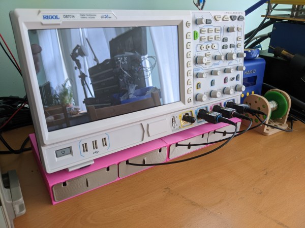
An oscilloscope with its probes stored in drawers below it

Clever Scope Probe Drawers Keep Your Workbench Tidy

Probes are an essential component of a good oscilloscope system, but they have the nasty habit of cluttering up your workbench. If you have a four-channel scope, it’s not just several meters of cable that get in the way everywhere, but also four sets of all those little clips, springs, cable markers, and adjustment screwdrivers that need to be stored safely.

[Matt Mets] came up with a clever solution to this problem: a 3D printed cable organizer that neatly fits below your scope. It has four drawers, each of which has enough space to store a complete probe and a little compartment for all its accessories. A cable cutout at the front allows you to keep the probes plugged in even when they’re not in use.

It’s a beautifully simple solution to a common problem, and with the STL files available on Printables anyone with a cluttered workbench can build one for themselves. If, however, you’d like to keep those probes even closer at hand, have a look at these probe caddies. Continue reading “Clever Scope Probe Drawers Keep Your Workbench Tidy”

Make Your Own Current Clamp Probe

If you want to measure AC or DC current with an oscilloscope, a current clamp is a great way to do it. The clamp surrounds the wire, so you don’t need to break the connection to take your measurements. These used to be expensive, although we’ve seen some under $100, if you shop. We don’t know if it was cost or principle that motivated [Electronoobs] to build his own current clamp, but he did.

This probe design is little more than a 3D printed case, an old power supply toroid, and a conventional alligator clamp to make the business end. The sensor uses a ferrite core and a hall effect sensor. The ferrite toroid is split in half, one half in each side of the clamp. An opamp circuit provides a gain of 100 to boost the hall effect sensor’s output.

In addition to building a homebrew probe, the video also shows a teardown of a Hantek current probe and explains the theory behind the different kinds of current probes, including some tricks like using a compensation winding to prevent core magnetization.

Does it work? You bet. After calibration, it did just fine. It’s not as pretty as a $100 unit, but beauty is in the eye of the beholder, and we are suckers for homebrew gear so we will say it is certainly more interesting. If you have a fair junk box (and a 3D printer), this probe could be made very inexpensively. The hall effect and a BNC connector are likely to be the most expensive parts. Even if you bought everything and used a non-printed case, we would be hard-pressed to think you’d spend more than $25.

If you want to see how the big boys do it, Keysight had a good break down last year. We’ve seen other homebrew builds for current probes and some of them are very accurate.

Continue reading “Make Your Own Current Clamp Probe”

Review: The O-scope Mayer D4/WG5 Calibrated Fleshy Test Probe

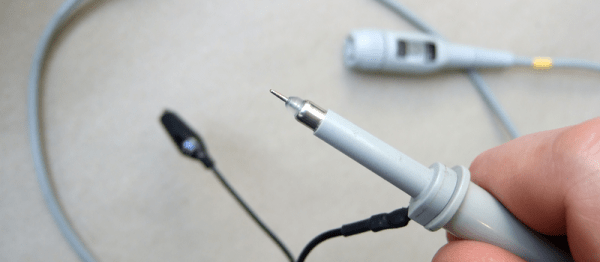
A selection of probes, from [Jim Williams'] Linear Technology app note 72.
A selection of probes, from [Jim Williams’] Linear Technology app note 72.
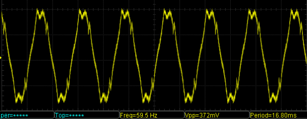
It’s not often that we are shown an entirely new class of test equipment here at Hackaday, so it was with some surprise that we recently received the new O-scope Mayer offering. If your most simple piece of test equipment is your own finger, able to measure temperature, detect voltage, and inject a 50 or 60 Hz sine wave, then what they have done is produce a synthetic analogue with a calibrated reading. The idea is that where previously you could only say “Too hot!”, or “High voltage!”, you should now be able to use their calibrated probe to gain an accurate reading.

The O-scope Mayer D4/WG5 Calibrated Fleshy Test Probe is a roughly 4″ (100mm) long cylinder of their InteliMeat™ synthetic finger analogue terminated with a calibrated matching unit and a BNC socket. In the box aside from the instruction leaflet is a BNC lead through which you can connect it to your oscilloscope.

Continue reading “Review: The O-scope Mayer D4/WG5 Calibrated Fleshy Test Probe”

How An Oscilloscope Probe Works, And Other Stories

The oscilloscope is probably the most versatile piece of test equipment you can have on your electronics bench, offering a multitude of possibilities for measuring timing, frequency and voltage as well as subtleties in your circuits revealed by the shape of the waveforms they produce.

On the front of a modern ‘scope is a BNC socket, into which you can feed your signal to be investigated. If however you simply hook up a co-axial BNC lead between source and ‘scope, you’ll immediately notice some problems. Your waveforms will be distorted. In the simplest terms your square waves will no longer be square.

Why is this? Crucial to the operation of an oscilloscope is a very high input impedance, to minimise current draw on the circuit it is investigating. Thus the first thing that you will find behind that BNC socket is a 1 megohm resistor to ground, or at least if not a physical resistor then other circuitry that presents its equivalent. This high resistance does its job of presenting a high impedance to the outside world, but comes with a penalty. Because of its high value, the effects of even a small external capacitance can be enough to create a surprisingly effective low or high pass filter, which in turn can distort the waveform you expect on the screen.

The answer to this problem is to be found in your oscilloscope probe. It might seem that the probe is simply a plug with a bit of wire to a rigid point with an earth clip, but in reality it contains a simple yet clever mitigation of the capacitance problem.

Continue reading “How An Oscilloscope Probe Works, And Other Stories”

WTF Are Ground Loops?

These magical creatures crop up out of nowhere and fry your electronics or annoy your ear holes. Understanding them will doubtless save you money and hassle. The ground loop in a nutshell is what happens when two separate devices (A and B) are connected to ground separately, and then also connected to each other through some kind of communication cable with a ground, creating a loop. This provides two separate paths to ground (B can go through its own connection to ground or it can go through the ground of the cable to A and then to A’s ground), and means that current may start flowing in unanticipated ways. This is particularly noticeable in analog AV setups, where the result is audio hum or visible bars in a picture, but is also sometimes the cause of unexplained equipment failures. Continue reading “WTF Are Ground Loops?”

DIY Active Sub-GHz Differential Scope Probe

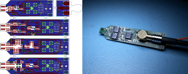
Fancy measurement gear is often expensive to buy, but some bits of kit are entirely DIY’able if you’re willing to put a little work into the project. [Christer Weinigel] needed to get some measurements of a differential clock signal that was ticking away around 500 MHz. El-cheapo probes aren’t going to cut it here. They won’t have the bandwidth and most off-the-rack probes are single-ended, that is they’re referenced to ground. [Christer] needed the difference between two balanced signals, neither of which is grounded. In short, [Christer] needed a high-frequency active differential oscilloscope probe, and they’re not cheap. So he built one himself.

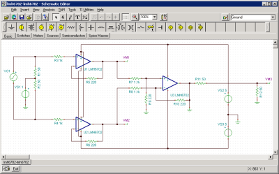
simulation-schematicThe circuit in the probe is really just an instrumentation amplifier design with a modified input stage and a 50 ohm output impedance. (See this article on in-amps if you need to brush up.) With higher frequencies like this, it’s going to be demanding on the op-amp, so [Christer] spent some time simulating the circuit to make sure it would work with his chosen part. Then he made up a bunch of PCB designs and had them made. Actual results matched fairly well with the simulation.

With some minor tweaking on the input damping resistors, he got a tool that’s dead flat up to 300 MHz, and totally usable up to 850 MHz. If you tried to buy one of these, it’d set you back the cost of a few hundred lattes, but this one can be made for the price of one or two if you get the PCBs done cheaply. Of course, the design files are available for your own use. Kudos [Christer].

Edit: By total coincidence, Bil Herd just posted a video intro to differential signals. Go check it out.

And thanks to [nebk] for the tip!