[Matthias Blaicher] may think this isn’t a big deal when it comes to the amount of work he put into the hack. But for us, anything that extends the functionality of the versatile yet affordable Rigol DS1052E is a win. In this case he’s taken a previous hack and made it work for more people by extending the functionality of the WFM file format viewer.
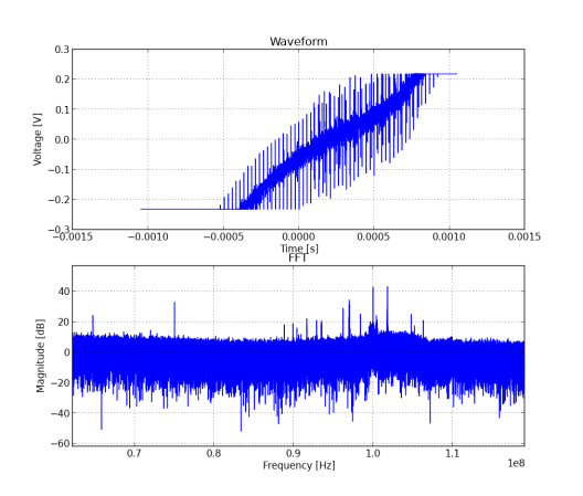
[Dexter2048] pulled off the original hack which allows this oscilloscope to be used as a spectrum analyzer. [Matthias] didn’t want the tool to be limited to running only on Windows systems so he got to work. This isn’t quite as easy as sounds because the only part of the original code that was released is the parser itself. [Matthias] had to build everything up from that starting point. His software uses standard Python to parse the WFM file and reformat the data. The features included in the current version allow you to export data as a CSV file and even plot the waveform and FFT as seen above.