There’s no piece of technology that has been more useful, more influential on the next generation of sysadmins and engineers, and more polarizing than the Raspberry Pi. For $35 (or just $5), you get a complete single board computer, capable of running Linux, and powerful enough to do useful work. For the 2016 Hackaday Prize, [Arsenijs] has created the perfect Raspberry Pi project. It’s everything you expect a Pi-powered project to be, and more.
While the Raspberry Pi, and the community surrounding the Raspberry Pi, get a lot of flak for the relatively simple approach to most projects which are effectively just casemods, critics of these projects forget the historical context of tiny personal computers. Back in the early ‘aughts, when Mini ITX motherboards were just being released, websites popped up that would feature Mini ITX casemods and nothing else. While computers stuffed into an NES, an old radio, or the AMD logo are rather banal projects today, I assure you they were just as pedestrian 15 years ago as well. Still, the creators of these Mini ITX case mods became the hardware hackers of today. It all started with simple builds, a Dremel, and some Bondo.
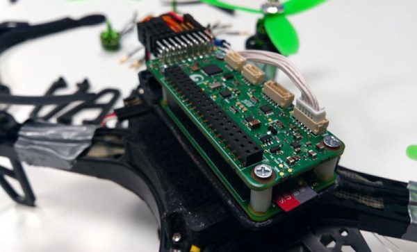
[Arsenijs] takes his Raspberry Pi project a bit further than a simple casemod, drawing influence from a Raspberry Pi smartphone, a Raspberry Pi security system, a Portable Raspberry Pi, and a Raspberry Pi wrist computer. These are all excellent projects in their own right, but [Arsenijs] is putting his own special twist on the project: he’s using a Raspberry Pi, and a few Raspberry Pi accessories.
While this project is first and foremost a Raspberry Pi project, [Arsenijs] isn’t limiting himself to the platform with the Broadcom chip. The team behind this Raspberry Pi project was busy porting the project to Odroid when the Banana Pi came out. This changed everything, a refactor was required, and then the Orange Pi was announced. Keeping up with technology is hard, and is a big factor in why this Raspberry Pi project hasn’t delivered yet. You can say a lot of things about the Raspberry Pi foundation, but at least their boards make a good attempt at forward compatibility.
Already [Arsenijs]’ Raspberry Pi project is one of the more popular projects on Hackaday.io, and is in the running for being one of the most popular projects in this year’s Hackaday Prize. Whether that popularity will translate into a minor win for this year’s Hackaday Prize remains to be seen, but it seems for [Arsenijs] that doesn’t matter; he’s already on the bleeding edge of Raspberry Pi projects.