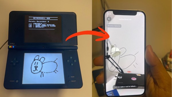
A New Raspberry 5 DSI Cable Makes Using Screens Easier

Arguably the greatest strength of the Raspberry Pi is the ecosystem — it’s well-supported by its creators and the aftermarket. At the same time, the proliferation of different boards has made things more complicated over the years. Thankfully, though, the community is always standing by to help fix any problems. [Rastersoft] has stepped up in this regard, solving an issue with the Raspberry Pi 5 and DSI screen cables.

The root cause is that the DSI cable used on the Raspberry Pi 5 has changed relative to earlier boards. This means that if you use the Pi 5 with many existing screens and DSI cables, you’ll find your flat ribbon cable gets an ugly twist in it. This can be particularly problematic when using the cables in tight cases, where they may end up folded, crushed, or damaged.

[Rastersoft] got around this by designing a new cable that avoided the problem. It not only solves the twist issue, but frees up space around the CPU if you wish to use a cooler. Thanks to modern PCB houses embracing flexible boards, it’s easy to get it produced, too.

This is a great example of the democratization of PCB and electronics production in general. 20 years ago, you wouldn’t be able to make a flex cable like this without ordering 10,000 of them. Today, you can order a handful for your own personal use, and share the design with strangers on a whim. Easy, huh? It’s a beautiful world we live in.

Displays We Love Hacking: DSI

We would not be surprised if DSI screens made up the majority of screens on our planet at this moment in time. If you own a smartphone, there’s a 99.9% chance its screen is DSI. Tablets are likely to use DSI too, unless it’s eDP instead, and a smartwatch of yours definitely will. In a way, DSI displays are inescapable.

This is for a good reason. The DSI interface is a mainstay in SoCs and mobile CPUs worth their salt, it allows for higher speeds and thus higher resolutions than SPI ever could achieve, comparably few pins, an ability to send commands to the display’s controller unlike LVDS or eDP, and staying low power while doing all of it.

There’s money and power in hacking on DSI – an ability to equip your devices with screens that can’t be reused otherwise, building cooler and cooler stuff, tapping into sources of cheap phone displays. What’s more, it’s a comparably underexplored field, too. Let’s waste no time, then!

Decently Similar Internals

DSI is an interface defined by the MIPI Alliance, a group whose standards are not entirely open. Still, nothing is truly new under the sun, and DSI shares a lot of concepts with interfaces we’re used to. For a start, if you remember DisplayPort internals, there are similarities. When it comes to data lanes, DSI can have one, two or four lanes of a high-speed data stream; smaller displays can subsist with a single-lane, while very high resolution displays will want all four. This is where the similarities end. There’s no AUX to talk to the display controller, though – instead, the data lanes switch between two modes.

Continue reading “Displays We Love Hacking: DSI”

How To Drive Smartphone Screens Over HDMI

Compared to most small LCDs sold to makers, smartphone screens boast excellent color, brightness, and insanely high resolution. Unfortunately, driving them is rarely straightforward. In an attempt to make it easier, [peng-zhihui] set about developing tools to allow such screens to be driven from a simple HDMI feed. For those whose Chinese is a little rusty, the Google Translate link might prove useful.

The first attempt was using Toshiba’s TC358870XBG ASIC, capable of driving screens over MIPI DSI 1.1 from an HDMI input. [peng-zhihui] designed a simple test module for the chip based on the company’s evaluation board design, with [ylj2000] providing software to help get that solution off the ground.

However, for now that solution is imperfect, so [peng-zhihui] also experimented with the Longxun LT6911 HDMI to MIPI driver. While cheap, information on the part is scarce, and the company’s own source code for using the hardware is only accessible by signing an NDA. However, [peng-zhihui] made pre-compiled firmware available for those that wish to work with the hardware.

[peng-zhihui] has put these learnings to good use, building a power bank with a MIPI screen using what appears to be the Longxun chip. The device can supply power over USB and also act as an HDMI display.

While it’s early days yet, and driving these screens remain difficult, it’s great to see hackers getting out there and finding a way to make new parts work for them. We’ve seen similar work before, using an FPGA rather than an off-the-shelf ASIC. If you’ve found your own way to get these high-end displays working, be sure to drop us a line!

[Thanks to peterburk for the tip!]

A Raspberry Pi Tablet, With A DSI Screen

Since the Raspberry Pi arrived back in 2012, we’ve seen no end of interesting and creative designs for portable versions of the little computer. They often have problems in interfacing with their screens, either on the very cheap models using the expansion port or on more expensive ones using an HDMI screen with associated controller and cabling. The official Raspberry Pi touchscreen has made life easier with its DSI convector, but as [jrberendt] shows us with this neat little tablet, there are other DSI-based options. This one uses a 5″ DSI touchscreen available through Amazon as well as a Pi UPS board to make a tablet that is both diminutive and self-contained.

Having fooled around ourselves in the world of Pi tablets we like this one for its clean look and a bezel that is little bigger than the screen itself. As is the case with so many Pi tablets though it has to contend with the bulk of a full-sized Model B board on its behind, making it more of a chunky brick than a svelte tablet. The screen has potential though, and we can’t help wondering whether there’s any mileage in pairing it with a much thinner Pi Zero board and a LiPo board for a slimmer alternative.

Probably the nicest Pi tablet we’ve brought you was this one, which managed to remain impressively slim despite its HDMI screen.

Putting An Out Of Work IPod Display To Good Use

[Mike Harrison] produces so much quality content that sometimes excellent material slips through the editorial cracks. This time we noticed that one such lost gem was [Mike]’s reverse engineering of the 6th generation iPod Nano display from 2013, as caught when the also prolific [Greg Davill] used one on a recent board. Despite the march of progress in mobile device displays, small screens which are easy to connect to hobbyist style devices are still typically fairly low quality. It’s easy to find fancier displays as salvage but interfacing with them electrically can be brutal, never mind the reverse engineering required to figure out what signal goes where. Suffice to say you probably won’t find a manufacturer data sheet, and it won’t conveniently speak SPI or I2C.

After a few generations of strange form factor exploration Apple has all but abandoned the stand-alone portable media player market; witness the sole surviving member of that once mighty species, the woefully outdated iPod Touch. Luckily thanks to vibrant sales, replacement parts for the little square sixth generation Nano are still inexpensive and easily available. If only there was a convenient interface this would be a great source of comparatively very high quality displays. Enter [Mike].

Outer edge of FPGA and circuit

This particular display speaks a protocol called DSI over a low voltage differential MIPI interface, which is a common combination which is still used to drive big, rich, modern displays. The specifications are somewhat available…if you’re an employee of a company who is a member of the working group that standardizes them — there are membership discounts for companies with yearly revenue below $250 million, and dues are thousands of dollars a quarter.

Fortunately for us, after some experiments [Mike] figured out enough of the command set and signaling to generate easily reproduced schematics and references for the data packets, checksums, etc. The project page has a smattering of information, but the circuit includes some unusual provisions to adjust signal levels and other goodies so try watching the videos for a great explanation of what’s going on and why. At the time [Mike] was using an FPGA to drive the display and that’s certainly only gotten cheaper and easier, but we suspect that his suggestion about using a fast micro and clever tricks would work well too.

It turns out we made incidental mention of this display when covering [Mike]’s tiny thermal imager but it hasn’t turned up much since them. As always, thanks for the accidental tip [Greg]! We’re waiting to see the final result of your experiments with this.

Finally, An Official Display For The Raspberry Pi

Yes, finally, and after years of work and countless people complaining on forums, there is a proper, official display for the Raspberry Pi.

It’s a 7-inch display, 800 x 480 pixel resolution, 24-bit color, and has 10-point multitouch. Drivers for the display are already available with a simple call of sudo apt-get update, and the display itself is available at Newark, the Pi Store (sold out) and Element14. There’s even a case available, and a stand ready to be sent off to a 3D printer.

As for why it took so long for the Raspberry Pi foundation to introduce an official display for the Pi, the answer should not be surprising for any engineer. It’s EMC, or electromagnetic compliance. The DPI (Display Parallel Interface) for the Pi, presented on the expansion header and used by the GertVGA adapter allows any Pi to drive two displays at 1920 x 1024, 60FPS. This DPI interface is an electrical nightmare that spews RF interference everywhere it goes.

raspberry-pi-touchscreen-thumb
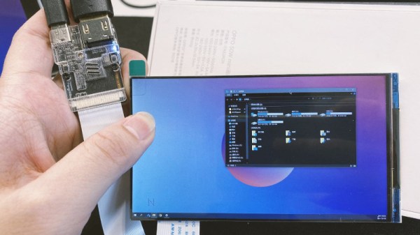
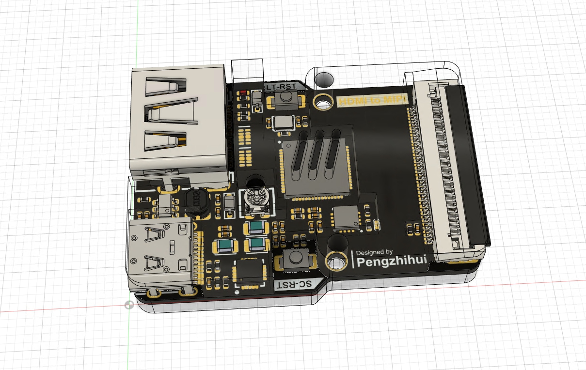
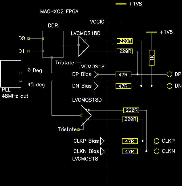
The new display could have used the DSI (Display Serial Interface) adapter, or the small connector on the Pi that is not the camera connector. DSI displays are purpose-built for specific devices, though, and aren’t something that would or should be used in a device that will be manufactured for years to come. The best solution, and the design the Raspberry Pi foundation chose to go with, is a DPI display and an adapter that converts the Pi’s DSI output to something the display can understand.

The solution the Pi foundation eventually settled on is an adapter board that converts the DSI bus to DPI signalling. This of course requires an extra PCB, and the Foundation provided mounting holes so a Pi can connect directly to it.

While this is the first display to make use of the DSI interface, it will assuredly not be the last. The Pi Foundation has given us a way to use the DSI connector to drive cheap DPI displays. While the 800×480 resolution of the official display may be a bit small, there will undoubtedly be a few hardcore tinkerers out there that will take this adapter board and repurpose it for larger displays.

[Alex Eames] got his hands on the Pi Display a few weeks ago, you can check out his introductory video below.

Continue reading “Finally, An Official Display For The Raspberry Pi”

Hacklet 35 – BeagleBone Projects

The Raspberry Pi 2 is just barely a month old, and now that vintage console emulation on this new hardware has been nailed down, it’s just about time for everyone to do real work. You know, recompiling stuff to take advantage of the new CPU, figuring out how to get Android working on the Pi, and all that good stuff that makes the Pi useful.

It will come as no surprise to our regular readers that there’s another board out there that’s just as good in most cases, and in some ways better than the Pi 2. It’s the BeagleBone Black, and for this edition of the Hacklet, we’re focusing on all the cool BeagleBone projects on Hackaday.io.

lcdSo you have a credit card sized Linux computer and a small, old LCD panel. If it doesn’t have HDMI, VGA or composite input, there’s probably no way of getting this display working, right? Nope. Not when you can make an LCD cape for $10.

[Dennis] had an old digital picture frame from a while back, and decided his BeagleBone needed a display. A few bits of wire and some FPC connectors, and [Dennis] has a custom display for his ‘Bone. It’s better than waiting for that DSI display…

bed[THX1082] is making a bed for his son. This isn’t your usual race car bed, or even a very cool locomotive bed. No, this is a spaceship bed. Is your bed a space ship? No, I didn’t think so.

Most of the work with plywood, MDF, paint, and glue is done, which means the best feature of this bed – a BeagleBone Black with an LCD, buttons, a TV, and some 3D printed parts – is what [THX] is working on right now. He’s even forking a multiplayer networked starship simulator to run in the bed. Is your bed a starship simulator?

beer

Beer. [Deric] has been working on a multi-step fermentation controller using the BeagleBone Black. For good beer you need to control temperatures and time, lest you end up with some terrible swill that I’d probably still drink.

This project controls every aspect of fermentation, from encouraging yeast growth, metabolization of sugars, and flocculation. The plan is to use two circuits – one for heating and one for cooling – and a pair of temperature sensors to ensure the beer is fermenting correctly.


If you’re looking for more BeagleBone Projects, there’s an entire list of them over on Hackaday.io with GLaDOs Glasses, Flight Computers, and Computer Vision.