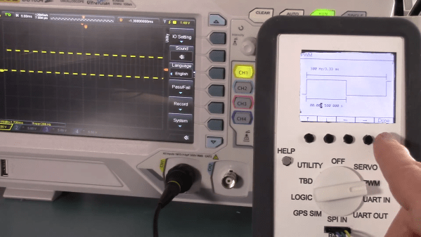
The basic test instrument suite — a bench power supply, a good multimeter and perhaps an oscilloscope — is extremely flexible, but not exactly “plug and play” when it comes to diagnosing problems with some common hardware setups. A problem with a servo driver, for example, might be easy enough to sort of with a scope, but setting everything up to see what’s going on with the PWM signal takes some time.
There’s got to be a better way to diagnose hobby electronics woes, and if [Bob Alexander] has his way, his “Logic Meter”, or something very close to it, will be the next must-have bench tool. The Logic Meter combines some of the functionality of an oscilloscope and a logic analyzer into a handy instrument that’s as easy to use as a multimeter. The Logic Meter’s probes connect to logic-level signals in a circuit and can be set up to capture or send serial data, either directly to or from a UART or via an SPI bus connection. There are also functions for testing servos and similar devices with a configurable PWM output. [Bob] rounds out the functionality with a GPS simulator and a simple logic analyzer, plus some utility functions.
The beauty part of the Logic Meter is that [Bob] has left where it goes next largely up to the community. He’s got a GitHub repo with details on the PIC32-based hardware, and the video below makes it clear that this is just a jumping-off point to further work that he hopes results in a commercial version of the Logic Meter. That’s a refreshing attitude, and we hope it pays off; from the look of a few of [Bob]’s retrocomputing makeovers, something like the Logic Meter could come in pretty handy.
Continue reading “Logic Meter Aims To Make Hobby Electronics Troubleshooting Easier”


