The Art Of The Silicon Chip

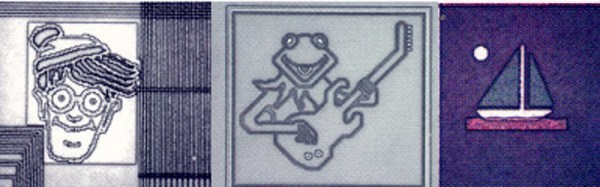
If you have followed the group of reverse engineers whose work on classic pieces of silicon we feature regularly here at Hackaday, you may well be familiar with the appearance of the various components that make up their gates and other functions. What you may not be familiar with, however, are the features that can occasionally be found which have no function other than the private amusement of the chip designers themselves. Alongside the transistors, resistors, and interconnects, there are sometimes little pieces of artwork inserted into unused spaces on the die, visible only to those fortunate enough to own a powerful microscope.

Fortunately those of us without such an instrument can also take a look at these works, thanks to the Smithsonian Institution, who have brought together a gallery of them on the web as part of their chip collection. In it we find cartoon characters such as Dilbert, favourites from children’s books such as Waldo, and the Japanese monster Godzilla. There are animals, cows, a leopard, a camel, and a porpoise, and of course company logos aplenty.

In a sense, these minuscule artworks are what our more strident commenters might describe as Not A Hack, but to dismiss them in such a manner would be to miss their point. Even in an age of huge teams of integrated circuit designers working with computerized tools rather than the lone geniuses of old with their hand drafting, we can still see little flashes of individuality with no practical or commercial purpose and with no audience except a very few. And we like that.

Also take a look at the work of [Ken Shirriff] for a masterclass in IC reverse engineering.

Self-Driving RC Cars With TensorFlow; Raspberry Pi Or MacBook Onboard

You might think that you do not have what it takes to build a self-driving car, but you’re wrong. The mistake you’ve made is assuming that you’ll be controlling a two-ton death machine. Instead, you can give it a shot without the danger and on a relatively light budget. [Otavio] and [Will] got into self-driving vehicles using radio controlled (RC) cars.

[Otavio] slapped a MacBook Pro on an RC car to do the heavy lifting and called it carputer. The computer reads Hall effect sensor data from the motor to establish distance traveled (this can be used to calculate speed) and watches the stream from a webcam perched on the chassis. These two sources are fed into a neural network using TensorFlow. You train the system by driving the vehicle manually through the course a few times and then let it drive itself.

In the video interview below, you get a look at the car and [Otavio] gives commentary on how the system works as we see playback of a few races, including the Sparkfun 2016 Autonomous Vehicle Competition. I apologize for the poor audio, they lost the booth lottery and were next door to an incredibly noisy robot band (video proof) so we were basically shouting at each other. But I think you’ll agree it’s worth it to get a look at the races. Continue reading “Self-Driving RC Cars With TensorFlow; Raspberry Pi Or MacBook Onboard”

LED display controlled by Bluetooth speaker

How Many Hacks In An LED Display?

There are so many nice hacks in [Joekutz]’s retro LED display project that it’s hard to know where to start. There’s his DIY LED display controlled by an Arduino UNO. To have some text or picture for the display, he’s wired the output of a Bluetooth speaker directly to the Arduino, and sends it speaker tones that encode the text to draw. And as if that wasn’t enough, he’s hacked a quartz driver board from an analog clock to use the display as a clock as well.

Let’s start with the LED matrix display, perhaps the best excuse for trying your hand at shift registers. This display uses two such 8-bit shift registers daisy chained together feeding two 8-bit Darlington arrays. The display has ten rows of sixteen columns, and you guessed it, the columns are controlled by the sixteen shift registers. Two Arduino pins tell the shift registers which column to turn on. The rows are turned on and off using ten transistors controlled by ten more Arduino pins. Scanning at 80 frames per second he gets a nice, flickerless display.

To make both the LED matrix circuit board and the control board, [Joekutz] carved out isolation paths in copper clad boards using his homemade CNC mill. Be sure to check out the first video below to see his misadventures with it that ultimately led to his gorgeous boards.

Continue reading “How Many Hacks In An LED Display?”

The Other Kind Of Phone Hacking

While it’s true that your parts bin might have a few parts harvested from outdated devices of recent vintage, there’s not much to glean anymore aside from wall warts. But the 3×48-character LCD from [Kerry Wong]’s old Uniden cordless landline phone was tempting enough for him to attempt a teardown and reverse engineering, and the results were instructive.

No data sheet? No problem. [Kerry] couldn’t find anything out about the nicely backlit display, so onto the logic analyzer it went. With only eight leads from the main board to the display module, it wasn’t likely to be a parallel protocol, and the video below shows that to be the case. A little fiddling with the parameters showed the protocol was Serial Peripheral Interface, but as with other standards that aren’t exactly standardized, [Kerry] was left with enough ambiguity to make the analysis interesting. Despite a mysterious header of 39 characters, he was able in the end to drive the LCD with an Arduino, and given that these phones were usually sold as a bundle with a base and several handsets, he ought to have a nice collection of displays for the parts bin.

With how prevalent this protocol has gotten, [Kerry]’s post makes us want to get up to speed on the basics of SPI. And to buy a logic analyzer too.

Continue reading “The Other Kind Of Phone Hacking”

Hackaday Prize Entry: The FPGA Commodore

The history of Commodore 8-bit computers ends with a fantastically powerful, revolutionary, and extraordinarily collectible device. The Commodore 65 was the chicken lip’ last-ditch effort to squeeze every last bit out of the legacy of the Commodore 64. Basically, it was a rework of a 10-year-old design, adding advanced features from the Amiga, but still retaining backwards compatibility. Only 200 prototypes were produced, and when these things hit the auction block, they can fetch as much as an original Apple I.

For their Hackaday Prize entry, resident hackaday.io FPGA wizard [Antti Lukats] and a team of retrocomputing enthusiasts are remaking the Commodore 65. Finally, the ultimate Commodore 8-bit will be available to all. Not only is this going to be a perfect replica of what is arguably the most desirable 8-bit computer of all time, it’s going to have new features like HDMI, Ethernet, and connections for a lot of FPGA I/O pins.

The PCB for this project is designed to fit inside the original case and includes an Artix A200T FPGA right in the middle of the board. HDMI and VGA connectors fill the edges of the board, there’s a connector for a floppy disk, and the serial port, cartridge slot, and DE9 joystick connectors are still present.

You can check out an interview from the Mega65 team below. It’s in German, but Google auto-generated and auto-translated captions actually work really, really well.

Continue reading “Hackaday Prize Entry: The FPGA Commodore”

Automate The Freight: Maritime Drone Deliveries

Ships at sea are literally islands unto themselves. If what you need isn’t on board, good luck getting it in the middle of the Pacific. As such, most ships are really well equipped with spare parts and even with raw materials and the tools needed to fabricate most of what they can’t store, and mariners are famed for their ability to make do with what they’ve got.

But as self-sufficient as a ship at sea might be, the unexpected can always happen. A vital system could fail for lack of a simple spare part, at best resulting in a delay for the shipping company and at worst putting the crew in mortal danger. Another vessel can be dispatched to assist, or if the ship is close enough ashore a helicopter rendezvous might be arranged. Expensive options both, which is why some shipping companies are experimenting with drone deliveries to and from ships at sea. Continue reading “Automate The Freight: Maritime Drone Deliveries”

You Won’t Believe That Fidget Spinners Are Obvious Clickbait!

I don’t know why fidget spinners are only getting popular now. They’ve been selling like hotcakes on Tindie for a year now, and I’ve been seeing 3D printed versions around the Internet for almost as long. Nevertheless, fidget spinners — otherwise known as a device to turn a skateboard bearing into a toy — have become unbelievably popular in the last month or so. Whatever; I’m sure someone thinks my complete collection of Apollo 13 Pogs from Carl’s Jr. with modular Saturn V Pog carry case and aluminum slammer embossed with the real Apollo 13 mission patch is stupid as well.

However, a new fad is a great reason to drag out an oscilloscope, measure the rotation of a fidget spinner, take a video of the whole endeavor, and monetize it on YouTube. That’s just what [Frank Buss] did. It’s like he’s printing money at this point.

The measurement setup for this test is simple enough. [Frank] connected a small solar cell to the leads of his $2k oscilloscope, and placed the cell down on his workbench. This generated a voltage of about 28mV. Spinning the fidget spinner cast a shadow over the cell that was measured as a change in voltage. Oscilloscopes measure frequency, and by dividing that frequency by three, [Frank] calculated his fidget spinner was spinning at the remarkable rate of 2200 RPM.

Is this a stupid use of expensive equipment? Surprisingly no. The forty thousand videos on YouTube demonstrating a “99999+ RPM Fidget Spinner” all use cheap digital laser tachometers available for $20 on eBay. These tachometers top out at — you guessed it — 99999 RPM. Using only an oscilloscope and a solar cell [Frank] found in his parts drawer, he found an even better way to push the envelope of fidget spinner test and measurement.

Using this method, even an inexpensive 40MHz scope can reliably measure three-bladed fidget spinners up to 800,000,000 RPM. Of course, this calculation doesn’t take into account capacitance in the cell, you’ll need a margin for Nyquist, and everything within 20 meters will be destroyed, but there you go. A better way to measure the rotation speed of fidget spinners. It’s technically a hack.

You can check out [Frank]’s video of this experiment below. If you liked this post, don’t forget to like, rate, comment and subscribe for even more of the best Fidget Spinner news.

Continue reading “You Won’t Believe That Fidget Spinners Are Obvious Clickbait!”