A Breadboard In A Browser

[Flownez] sent in a tip that a port of the venerable Falstad circuit simulator is now available that doesn’t require Java (it uses HTML 5). This is a welcome port since some modern browsers (particularly Chrome) make it difficult to run Java applets and prevented the Falstad simulator’s execution.

spice2
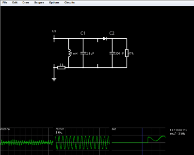
Like the original simulator, this one is great to show a classroom circuits and encourage building or studying circuits in the browser. There’s no extra software to install, which is handy for an impromptu demo. Another cool feature is the visualization of current flow as animated dots. The dots move in the direction of the current flow and the speed of motion is proportional to the amount of current. Watching a capacitor charge with the moving dots is very illustrative. You can also view data in a scope format or hover the mouse over things to read their values.

You can open a blank circuit and add quite a few components (use the right click button on your mouse or the menu to add components and wires). However, you can also pick from a number of predefined circuits ranging from the simple (a voltage divider, for example) to the illustrative (a PLL frequency doubler comes to mind). There’s even an AM radio (see below) that you can tune to find several “stations” by varying the tuning capacitor’s value. Circuit elements include many types of analog and digital components.

Continue reading “A Breadboard In A Browser”

Interactive Software To Solve Crosstalk Problems

A link to this video demonstrating PCB cross-talk ended up in my mailbox the other day as I tend to stay on the mailing lists of the some of the high end CAD companies. There are some really interesting and powerful “mega-tools” that do things like plot noise density for decoupling analysis and extremely high speed timing analysis, though the costs of these tools are commensurate with their capabilities. This one is part of the Mentor Graphics PCB Simulation software.

The tool shown does the math needed to predict the induced voltage noise (cross-talk) generated by the proximity of noise sources to the noise susceptible elements, and the tool does so interactively. This is remarkable… in the past we would calculate some examples of trace width, spacing, and the type of signals involved, and then generate some rules of thumb that we tried to apply during the layout process. It was an educated guess that was sometimes not as close as we would have liked.

Virtual Scope Showing Predicted Crosstalk
Virtual Scope Showing Predicted Cross-talk


The cool part of this software is the interactive nature. One can learn the effects of placement on cross-talk in real time, which helps build an intuitive understanding.

I will add the standard disclaimer that a tool is exactly that, a tool, and it only represents an approximation of real life at best. It’s tempting to design to the tool itself, and many engineers have learned the limitation of a tool the hard way. Instead think of the tool as another opinion, or as mentioned, a learning aid to gather an intuitive feel for the effects of placement on circuit performance.

ASAP 3 – The Almost Simple As Possible Computer

ASAP-3 12 - LED Display

[Pong] has joined an elite club of people who have designed and built their own computer – including a CPU created from discrete 7400 series logic. His computer is the  Almost Simple As Possible Computer 3 (ASAP-3). ASAP-3 is not a completely new design. The architecture is based upon the SAP series of computers from Albert Malvino’s book, Digital Computer Electronics. [Pong] looked at quite a few of the “modern retro” computers such as Magic-1Big Mess o’ Wires 1, and the Duo. These computers were beyond his skill levels back then, so he began to build his own system. His primary design goal was to be able to run a 4 function calculator program.

One thing that can’t be stressed enough is the fact that [Pong] made his design work much easier by using lots of simulation. His tool of choice was Proteus Design Suite. While simulation can’t solve every problem, it can often help in verifying that a given design is sound. The ASAP-3’s instruction set is microcode, based upon the 8085 series instruction set. The microcode itself is stored on Flash ROMS. Using microcode makes ASAP-3 very flexible. Don’t have a machine instruction you need? No problem – just write one up. When all was said and done, [Pong] had over 100 instructions spread over 3 Flash ROM chips.

The hardware was only half the battle – [Pong] found writing the software just as challenging. He wrote all the software by hand in his own machine code. This is where the simulation mentioned above really saved him some time. Even with simulation he still ran into some problems. The ASAP-1 is limited to a clock speed of around 500kHz. Above that, glitches from the ROM chips start triggering the asynchronous inputs in some of the registers. [Pong] doesn’t have a logic analyzer on hand, so he wasn’t able to track this one down further. He also found a (update simulation only) issue with the carry bit on the 74LS181 bit slice ALU. In certain circumstances the carry bit would not propagate correctly. [Pong] corrected this by using a ROM as a look up table replacement for certain ‘181 functions. Even with these limitations, this is still a great hack!

Continue reading “ASAP 3 – The Almost Simple As Possible Computer”

On Not Designing Circuits With Evolutionary Algorithms

[Henrik] has been working on a program to design electronic circuits using evolutionary algorithms. It’s still very much a work in progress, but he’s gotten to the point of generating a decent BJT inverter after 78 generations (9 minutes of compute time), as shown in the .gif above.

To evolve these circuits, [Henrik] told a SPICE simulation to generate an inverter with a 5V power supply, 2N3904 and 2N3906 transistors, and whatever resistors were needed. The first dozen or so generations didn’t actually do anything, but after 2000 generations the algorithm produced a circuit nearly identical to the description of a CMOS inverter you’d find in a circuit textbook.

Using evolution to guide electronic design is nothing new; an evolutionary algorithm and a a few bits of Verilog can turn an FPGA into a chip that can tell the difference between a 1kHz and 10kHz tone with extremely minimal hardware requirements. There’s also some very, very strange stuff that happened in this experiment; the evolutionary algorithm utilized things that are impossible for a human to program and relies on magnetic flux and quantum weirdness inside the FPGA.

[Henrik] says his algorithm didn’t test for how much current goes through the transistors, so implementing this circuit outside of a simulation will destroy the transistors and emit a puff of blue smoke. If you’d like design your own circuits using evolution, [Henrik] put all the code in a git for your perusal. It’s damn cool as it stands now, and once [Henrik] includes checking current and voltage in each component his project may actually be useful.

Soccer Simulator Rules A Child’s Birthday Party

[youtube=http://www.youtube.com/watch?v=gKACRU4LKfM&w=470]

Being a dedicated father, soccer coach, general tinkerer, and electrical engineer, [Dave] decided to build a soccer simulator video game for his son’s 6th birthday party. The concept behind the game is to put a soccer ball on a tee and have an eager line of six-year-olds kick the ball into the goal. A video of a goalie is projected behind the net, and sensors in the goal will determine if the player scored a goal or not.

The first part of [Dave]’s project was getting footage of a goalie diving for a soccer ball. Luckily, [Dave] is friends with [Mark Macdonald], a former NCAA goalie. After 10 minutes in the park with [Mark] and a 720p camera, [Dave] had all the footage needed to build his video game.

To detect where the soccer ball passed into the goal, [Dave] built a small soccer goal studded with infrared LEDs and infrared beam break sensors. Combined with a small switch underneath the ball tee, the software knows the time of flight and where the ball crossed into the goal. The game processes these two numbers to determine if it’s a goal, or was caught by the retired pro goalie.

The kids at the birthday party lined up to play [Dave]’s soccer game – a huge achievement getting 6-year-olds to wait their turn. We admit that we’d like to have a go at this game, although we’re pretty sure we saw an arcade version of this game years and years ago.

Simulated Dashboard For A Simulated Race

Simulators might have lost their cool for a lot of gamers, but [Fergo] is trying for a comeback. He built an electronic dashboard for a car racing simulator.

[Fergo] spends most of his track time on iRacing, an MMO racing simulator. Possibly due to a little bit of influence from Formula 1 steering wheels, he wanted to add to his dashboard that included Microsoft racing wheel. The dashboard includes RPM lights, a gear indicator, five general buttons, a rotary encoder, and a pit limiter, rev limiter and low fuel indicators.

The build is powered a VB.NET app that connects the iRacing API to an Arduino. To get all those buttons and LEDs talking to the Arduino, [Fergo] used an IO expander that communicates over an I2C bus. It’s a surprisingly simple design that should scale well if [Fergo] ever decides to expand his cockpit. We’re not sure if it could handle controlling a 737, but it would be more than sufficient for a Cessna 172 or Mercury capsule.

Check out [Fergo] tearing around the track with his buttonbox dashboard after the break.

Continue reading “Simulated Dashboard For A Simulated Race”