With the advent of affordable 2.5 Gbit, 5 Gbit, and 10 Gbit consumer networking gear, more and more people are taking advantage of these higher networking speeds, with [This Does Not Compute] having used 10 Gbit SFP+ modules over regular Cat-5e copper to connect to a NAS in the next room. Only problem was that after a while these SFP+ modules began to start dropping frames. On taking a closer look at these modules, he found that they were running pretty hot: 40°C while idle. A teardown of one of these modules showed severe discoloration due to heat.
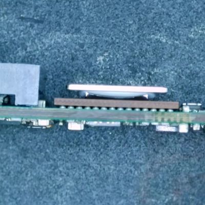
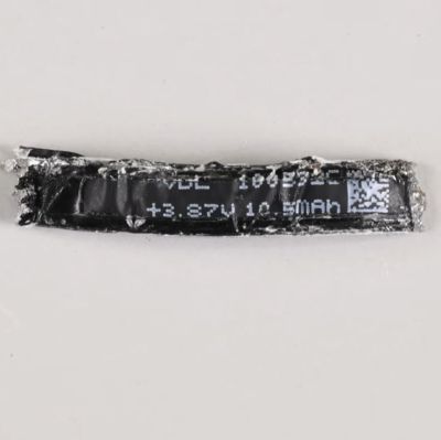
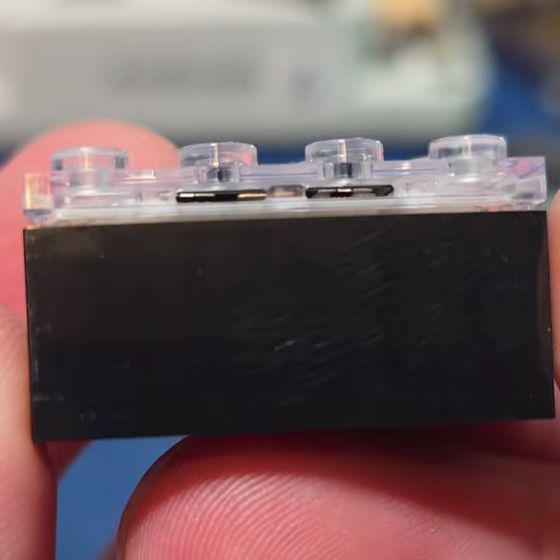
Inside these 10Gbit modules is the Marvell-branded Alaska X 88X3310/40P PHY, which despite the ‘low-power’ claims have a metal heatsink glued onto the actual IC and thermally coupled to the module’s metal enclosure. The other side of the PCB was quite discolored, further indicating how hot these modules run in operation. Some digging revealed that this can go up to around 2.5 watts.
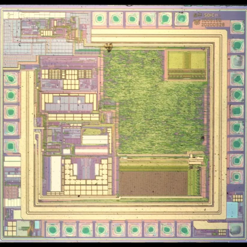
Perhaps the most fascinating part of this teardown is the discovery of an 8051-based MCU that’s responsible for telling the switch the module is put into that it is a 30-meter multi-mode fiber module, presumably for compatibility purposes. It’s definitely an interesting feature of these FS-branded SFP+ modules.
These old modules were replaced with Wiitek-branded modules that are supposed to use only up to around 1.5 watts in operation courtesy of a newer chipset, in the hope that these wouldn’t fry themselves. At idle these do however still run at 30 °C. As noted in the comments, it might be a good idea to have active airflow over high-speed networking gear like this, as they generally can get pretty hot and sometimes crispy.
The final solution for the video’s networking problem was to just run single-mode fiber to the room and use appropriate SFP+ modules for that, also because these run noticeably cooler. If you still have room in your cable ducts, that would seem to be the optimal solution.
Continue reading “Autopsy Of A Freshly Cooked 10Gbit SFP+ Network Adapter”