[j3tstream] wanted an easier way to monitor traffic on the roads in his area. Specifically, he wanted to monitor the roads from his car while driving. That meant it needed to be easy to use, and not too distracting.
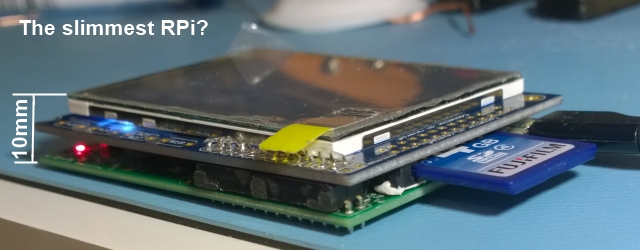
[j3tstream] figured he could use a Raspberry Pi to run the system. This would make things easy since he’d have a full Linux system at his disposal. The Pi is relatively low power, so it’s run from a car cigarette lighter adapter. [j3tstream] did have to add a custom power button to the Pi. This allows the system to boot up and shut down gracefully, preventing system files from being corrupted.
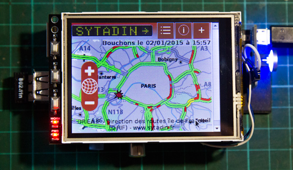
After searching eBay, [j3tstream] found an inexpensive 3.2″ TFT LCD touchscreen display that would work nicely for displaying the traffic data. The display was easy to get working with the Pi. [j3tstream] used the Raspbian linux distribution. His project page includes a link to download a Raspbian image that already includes the necessary modules to work with the LCD screen. Once the image is loaded, all that needs to be done is to calibrate the screen using built-in operating system functions.
The system still needed a data connection. To make things simple and inexpensive, [j3tstream] used a USB WiFi dongle. The Pi then connects to a WiFi hot spot built into his 4G mobile phone. To view the traffic map, [j3tstream] just connects to a website that displays traffic for his area.
The last steps were to automate as much as possible. After all, you don’t want to be fumbling with a little touch screen while driving. [j3tstream] made some edits to the LXDE autostart file. These changes automatically load a browser in full screen mode to the traffic website. Now when [j3tstream] boots up his Pi, it automatically connects to his WiFi hotspot and loads up local traffic maps.