This Robot Barfs Comics!

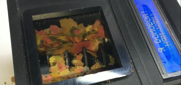
If there’s one thing that’s more fun than a comic, it’s a randomly generated comic. Well, perhaps that’s not true, but Reddit user [cadinb] wrote some software to generate a random comic strip and then built a robot case for it. Push a button on the robot and you’re presented with a randomly generated comic strip from the robot’s mouth.

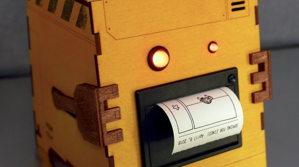
The software that [cadinb] wrote is in Processing, an open source programming language and “sketchbook” for learning to code if you’re coming from a visual arts background. The Processing code determines how the images are cropped and placed and what kind of background they get. Each image is hand drawn by [cadinb] and has information associated with it so the code knows what the main focus of the image is. Once the panels are created, the final image is passed on to a thermal printer for printing. Everything is controlled from a Python script running on a Raspberry Pi and the code, strip artwork, and case is all available online to check out.

Now that the comic can print, a case is needed for the printer and controls. [cadinb] designed a case in Illustrator after creating a prototype out of foam core. The design was laser cut and then coloured – the main body with fabric dye and the arms stained with coffee!

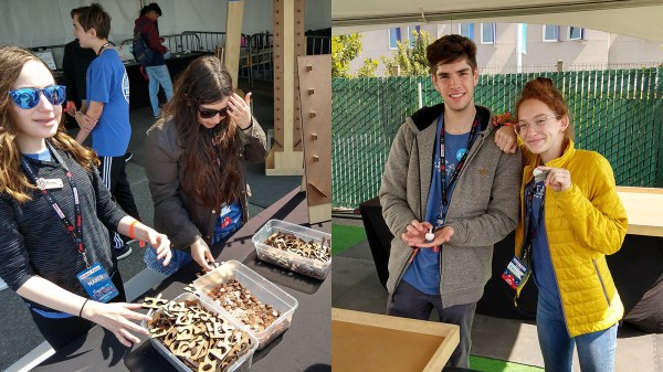
Now [cadinb] has a robot that can sit on his table at conventions and a fan can press a button and have a randomly generated comic strip printed out before their eyes! We have a neat article about printing a comic on a strand of hair, and one about bringing the Banana Jr. 6000 to life!

Continue reading “This Robot Barfs Comics!”

USB Reverse Engineering: A Universal Guide

Every hacker knows what it is to venture down a rabbit hole. Whether it lasts an afternoon, a month, or decades, finding a new niche topic and exploring where it leads is a familiar experience for Hackaday readers.

[Glenn ‘devalias’ Grant] is a self-proclaimed regular rabbit hole diver and is conscious that, between forays into specific topics, short-term knowledge and state of mind can be lost. This time, whilst exploring reverse engineering USB devices, [Glenn] captured the best resources, information and tools – for his future self as well as others.

His guide is impressively comprehensive, and covers all the necessary areas in hardware and software. After formally defining a USB system, [Glenn] refers us to [LinuxVoice], for a nifty tutorial on writing a linux USB driver for an RC car, in Python. Moving on to hardware, a number of open-source and commercial options are discussed, including GoodFET, FaceDancer, and Daisho – an FPGA based monitoring tool for analysing USB 3.0, HDMI and Gigabit Ethernet. If you only need to sniff low speed USB, here’s a beautifully small packet snooper from last year’s Hackaday prize.

This is a guide which is well-informed, clearly structured, and includes TL;DR sections in the perfect places. It gives due credit to LibUSB and PyUSB, and even includes resources for USB over IP.

If you’re worried about USB hacks like BadUSB, perhaps you should checkout GoodUSB – a hardware firewall for USB devices.

Header image: Ed g2s (CC-SA 3.0).


Linear Clock Is A Different Way To Look At Time

There are usually two broad user interfaces for clocks. On the one hand you’ve got the dial clock, the default display for centuries, with its numbered face and spinning hands. The other mode is some form of digital clock, where the current time is displayed directly as alphanumeric characters. They’re both useful representations of time, but they both have their limits.

Here’s a third model — the linear clock. [Jan Derogee] came up with it thanks to the inspiration of somewhat dubious run-ins with other kinds of clocks; we feel like this introductory video was made with tongue firmly planted in cheek. Whatever the inspiration, we find this idea clever and well executed. The running gear of the clock is just a long piece of M6 threaded rod and a stepper motor. A pointer connected to a nut rides on the rod, moving as the stepper rotates it. There are scales flanking the vertical rod, with the morning hours going up the left side and afternoon hours coming down the right. The threaded rod rotates one way for twelve hours before switching to the other direction; when the rotation changes, the pointer automatically swivels to the right scale. For alarms, [Jan] has brass rods running along each scale that make contact with the pointer; when they encounter a sliding plastic insulator to break the contact, it triggers an alarm. An ESP8266 controls everything and plays the audio files for the alarm.

Unusual clocks seem to be a thing with [Jan]. His other builds include this neat phosphorescent clock and YouTube subs counter, which is sure to turn heads along with this clock.

Continue reading “Linear Clock Is A Different Way To Look At Time”

Don’t Flake On Your Fish—Feed Them Automatically

We get it. You love your fish, but they can’t bark or gently nip at your shin flesh to let you know they’re hungry. (And they always kind of look hungry, don’t they?) One day bleeds into the next, and you find yourself wondering if you’ve fed them yet today. Or are you thinking of yesterday? Fish deserve better than that. Why not build them a smart fish feeder?

Domovoy is a completely open-source automatic fish feeder that lets you feed them on a schedule, over Bluetooth, or manually. This simple yet elegant design uses a small stepper motor to drive a 3D-printed auger to deliver the goods. Just open the lid, fill ‘er up with flakes, and program up to four feedings per day through the 3-button and LCD interface. You can even set the dosage, which is measured in complete revolutions of the auger.

It’s built around an ATMega328P, but you’ll have to spin your own board and put the feeder together using his excellent instructions. Hungry to see this feeder in action? Just swim past the break.

Can’t be bothered to feed your fish automatically? Train them to feed themselves.

Continue reading “Don’t Flake On Your Fish—Feed Them Automatically”

An Ultrasound Driver With Open Source FPGAs

Ultrasound imaging has been around for decades, but Open Source ultrasound has not. While there are a ton of projects out there attempting to create open ultrasound devices, most of this is concentrated on the image-processing side of things, and not the exceptionally difficult problem of pinging a sensor at millions of times a second, listening for the echo, and running that through a very high speed ADC.

For his entry into the Hackaday Prize, [kelu124] is doing just that. He’s building an ultrasound board that’s built around Open Hardware, a fancy Open Source FPGA, and a lot of very difficult signal processing. It also uses some Rick and Morty references, so you know this is going to be popular with the Internet peanut gallery.

The design of the ultrasound system is based around an iCE40 FPGA, the only FPGA with an Open Source toolchain. Along with this, there are a ton of ADCs, a DAC, pulsers, and a high voltage section to drive the off-the-shelf ultrasound head. If you’re wondering how this ultrasound board interfaces with the outside world, there’s a header for a Raspberry Pi on there, too, so this project has the requisite amount of blog cred.

Already, [kelu] has a working ultrasound device capable of sending pulses out of its head and receiving the echo. Right now it’s just a few pulses, but this is a significant step towards a real, working ultrasound machine built around a reasonably Open Source toolchain that doesn’t cost several arms and legs.

Biasing That Transistor: The Emitter Follower

We were musing upon the relative paucity of education with respect to the fundamentals of electronic circuitry with discrete semiconductors, so we thought we’d do something about it. So far we’ve taken a look at the basics of transistor biasing through the common emitter amplifier, then introduced a less common configuration, the common base amplifier. There is a third transistor amplifier configuration, as you might expect for a device that has three terminals: the so-called Common Collector amplifier. You might also know this configuration as the Emitter Follower. It’s called a “follower” because it tracks the input voltage, offering increased current capability and significantly lower output impedance.

The emitter follower circuit

Just as the common emitter amplifier and common base amplifier each tied those respective transistor terminals to a fixed potential and used the other two terminals as amplifier input and output, so does the common collector circuit. The base forms the input and its bias circuit is identical to that of the common emitter amplifier, but the rest of the circuit differs in that the collector is tied to the positive rail, the emitter forms the output, and there is a load resistor to ground in the emitter circuit.

As with both of the other configurations, the bias is set such that the transistor is turned on and passing a constant current that keeps it in its region of an almost linear relationship between small base current changes and larger collector current changes. With variation of the incoming signal and thus the  base current there is a corresponding change in the collector current dictated by the transistor’s gain, and thus an output voltage is generated across the emitter resistor. Unlike the common emitter amplifier this voltage increases or decreases in step with the input voltage, so the emitter follower is not an inverting amplifier.

Continue reading “Biasing That Transistor: The Emitter Follower”

Hacking For Learning And Laughs: The Makers Of Oakwood School

The tagline of Bay Area Maker Faire is “Inspire the Future” and there was plenty of inspiration for our future generation. We have exhibits encouraging children to get hands-on making projects to call their own, and we have many schools exhibiting their student projects telling stories of what they’ve done. Then we have exhibitors like Oakwood School STEAM Council who have earned a little extra recognition for masterfully accomplishing both simultaneously.

[Marcos Arias], chair of the council, explained that each exhibit on display have two layers. Casual booth visitors will see inviting hands-on activities designed to delight kids. Less obvious is that each of these experiences are a culmination of work by Oakwood 7th to 12th grade students. Some students are present to staff activities and they were proud to talk about their work leading up to Maker Faire with any visitors who expressed interest.

Continue reading “Hacking For Learning And Laughs: The Makers Of Oakwood School”