The 555 timer chip is a ubiquitous piece of technology that is oft-considered the hardcore way of doing things. Of course, the old timers out there will remind us that discrete transistors are the badass way of doing things, and tubes even more so. It’s not quite at the level of triodes and transformers, but Evil Mad Scientist’s discrete 555 kit is still an amazing piece of kit.
Instead of transistors and resistors etched into silicon as in the OG 555, [Windell] over at EMS turned the basic circuit inside a 555 into a mega-sized version using discrete components. Your parts bins need new scale if you’re going to work with this and other up-scaled hobby electronic components.
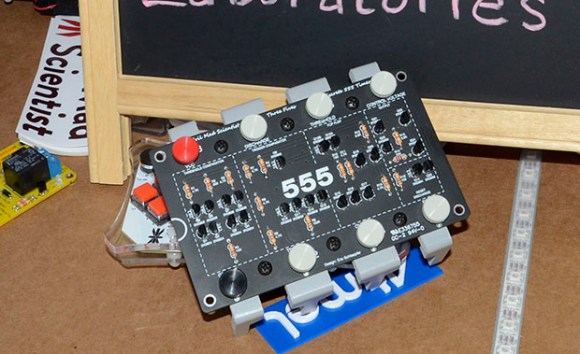
Although the integrated stand that makes the whole package look like an overgrown DIP doesn’t break out the signals on the board, it does include some neat screw terminals for alligator clips and bits of wire so this kit can be used in a circuit. Because it uses discrete components, you can also take a meter or scope to check out how a 555 chip works from the inside.