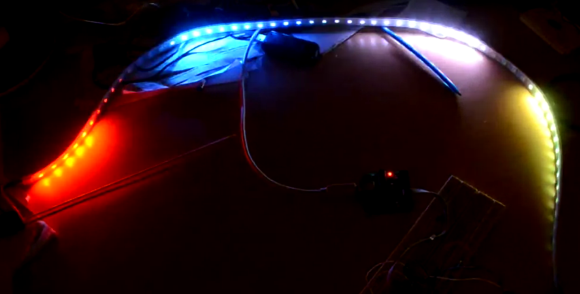
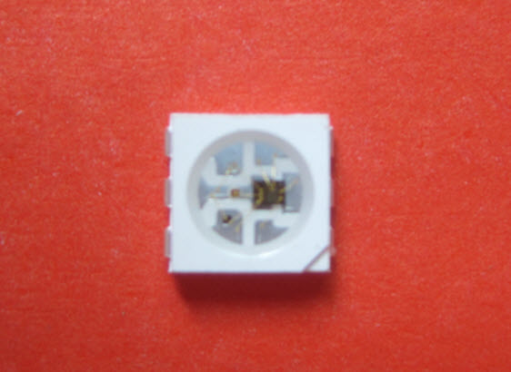
LED Tie Plays Tetris

tetris

[Bill] has been working with a gaggle of 8th graders this summer at a STEM camp, impressing them with his geeky attire such as an 8-bit and PCB ties, and an LED illuminated lab coat. The adolescent tinkerers asked him what he would be wearing on the last day. Not wanting to let the kids down, he whipped up an LED Tetris tie in an evening.

The Tetris board is a 20 x 4 grid of WS2811 based RGB LED strips, controlled by a Digispark dev board. Structurally, the tie is just two bits of card stock with the electronic bits sandwiched in between. and taped to a cheap clip-on. In the video below, the tie doesn’t have any sort of input to control the movement and rotation of blocks. [Bill] plans to update his tie with some rudimentary AI so it can play itself.

All the code is over on [Bill]’s git. It’s still a work in progress, but from the STEM student’s reaction, there’s a lot of potential in this tie.

Continue reading “LED Tie Plays Tetris”

WS2811 Can Be Addressed At 800kHz Using A 8MHz Clock

ws2811-running-at-8mhz

Timing is everything and that’s why most communication protocols require a very accurate clock source. The WS2811 LED strip controllers are no different. But [Danny] figured out a way to drive them reliably with an 8MHz clock source.

The WS2811 has become one of the most popular controllers for RGB pixels and strips alike. We’ve seen several hacks used to address them, including the 16MHz AVR technique that inspired [Danny] to take on this project. He planned to use that library but the 25-day shipping time for a 16MHz crystal drove home to invent a way to use the internal oscillator instead.

The gist of the hack is that he wrote assembly code to handle pairs of binary bit values. With a code block for each of the four possible combinations in hand he had to find a way to craft the conditional jumps to preserve accurate timing. After hitting the wall trying to solve this puzzle by hand he wrote a C++ program to solve it for home. The proof is in this video which shows one chip driving multiple Larson scanners on a single strip.

Continue reading “WS2811 Can Be Addressed At 800kHz Using A 8MHz Clock”

Building Huge Displays With LED Strips

Building RGB LED displays is one of the most interesting programming and engineering challenges we see here on Hackaday. Not only do the creators of large displays and LED cubes have to deal with the power requirements of driving a whole bunch of LEDs, but there’s also the issue of getting the frame rate high enough to display video. It’s a non-trivial task, but [Paul Stoffregen] has an interesting solution. He wrote an LED strip library that can control eight meter-long LED strips that can also be used on daisy chained Teensy 3.0 microcontrollers for really large displays.

[Paul]’s LED library works with LED strips based on the WS2811 LED controller IC. These chips are the most common controller chips for the individually controllable LED strips you can find at Adafruit or hundreds of Chinese resellers. The library requires DMA transfer to display images, so if you’re looking to build a ginormous RGB LED display, you might want to pick up a few of [Paul]’s Teensy 3.0 boards

[Paul] also created a Processing app that takes a video file and turns it into serial data for his LED strip library. You can check out a video of this app, library, and a 60×32 RGB LED display after the break.

Continue reading “Building Huge Displays With LED Strips”

A Blinky Fedora To Ring In The New Year

[Garrett Mace] decided to dress festive for New Year’s Eve. What he came up with is a fedora ringed in LEDs that react to music. The hardware uses 5050 LEDs on strips. Three of them encircle the head-gear providing a total of 114 RGB pixels. Each is a WS2811 module — a part which we’re seeing more and more of lately.

The video clip after the break starts off with a few minutes of demonstration. [Garrett] managed to code all kinds of animations for the hardware including several different styles of color sweeps and fades. You may start to think that the three bands always display the same patterns but keep watching and you’ll see a sparkle pattern that proves each dot can be addressed individually.

About 2:20 seconds into the video [Garrett] explains how he pulled it off and shows off the driver hardware. The strips are glued to a band of webbing that slides over the hat. The wires that drive the lights were fed through the center of some paracord and connect to an Arduino housed in a 3D printed case. Power is provided by a portable USB battery with a ShiftBrite shield and an MSGEQ7 chip complete the parts list.

Continue reading “A Blinky Fedora To Ring In The New Year”

Three Conceptual Approaches To Driving A WS2811 LED Pixel

driving-a-ws2811

[Cunning_Fellow] published a post with three proof-of-concept approaches to driving a WS2811 LED pixel. We looked at a project early in December that used an AVR microcontroller to drive the RGB package. [Cunning_Fellow] saw this, and even though he doesn’t have any of these parts on hand he still spent the time hammering out ways to overcome the timing issues involved with address the device. His motto is “put up or shut up” when it comes to criticizing projects featured on Hackaday. We love seeing someone pick up an idea and run with it.

The approach in all three cases aims to conserve clock cycles when timing the communications. This leaves the developer as many cycles as possible to perform other tasks than simply telling the lights what to do. One approach is an assembly routine that is just a shade slower but groups all 14 free cycles into one block. The next looks at using external 7400 series hardware. The final technique is good old-fashioned bit banging.

[Photo Credit]

Driving A WS2811 RGB LED Pixel

[Alan] has been working on driving this WS2811 LED module with an AVR microcontroller. It may look like a standard six-pin RGB LED but it actually contains both an LED module and a microcontroller to drive it. This makes it a very intriguing part. It’s not entirely simple to send commands to the module as the timing must be very precise. But once the communication has happened, the LED will remain the same color and intensity until you tell it otherwise. You can buy them attached to flexible strips, which can be cut down to as few as one module per segment. The one thing we haven’t figure out from our short look at the hardware is how each pixel is addressed. We think the color value cascades down the data line as new values are introduced, but we could be wrong. Feel free to discuss that in the comments.

The project focuses on whether or not it’s even possible to drive one of these pixels with a 16MHz AVR chip. They use single-wire communications at 800 kHz and this really puts a lot of demand on the microcontroller. He does manage to pull it off, but it requires careful crafting in assembly to achieve his timing constraints. You can see a quick clip of the LEDs fading between colors after the break.

Continue reading “Driving A WS2811 RGB LED Pixel”